Global high-mix volume high-speed PCBA manufacturer
9:00 -18:00, Mon. - Fri. (GMT+8)
9:00 -12:00, Sat. (GMT+8)
(Except Chinese public holidays)
Global high-mix volume high-speed PCBA manufacturer
9:00 -18:00, Mon. - Fri. (GMT+8)
9:00 -12:00, Sat. (GMT+8)
(Except Chinese public holidays)
HomePage > Blog > Knowledge Base > About USB PCB – All You Want to Know
Have you ever thought about how USB devices are able to transfer data efficiently and effectively? It's just magic that relies on the USB PCBs (printed circuit boards) that are a core element of USB functionality and connectivity. USB PCBs are an important component of all electronic industries that streamlines the charging and data transfer functionality of all devices such as mobile phones, laptops and other IoT devices.
In this guide, I will explain what USB PCBs are, what kinds of them exist, what their advantages are, and how one can design the latter in the best way. Why is it important to learn about USB on PCBs?
Whether you have an interest in technology, work as a hardware developer, or are interested, you will find out more about the design, functionality, and further development of USB 4.0 and Type-C. At the end of the discussion, the reader will understand how USB PCBs influence possible connectivity.
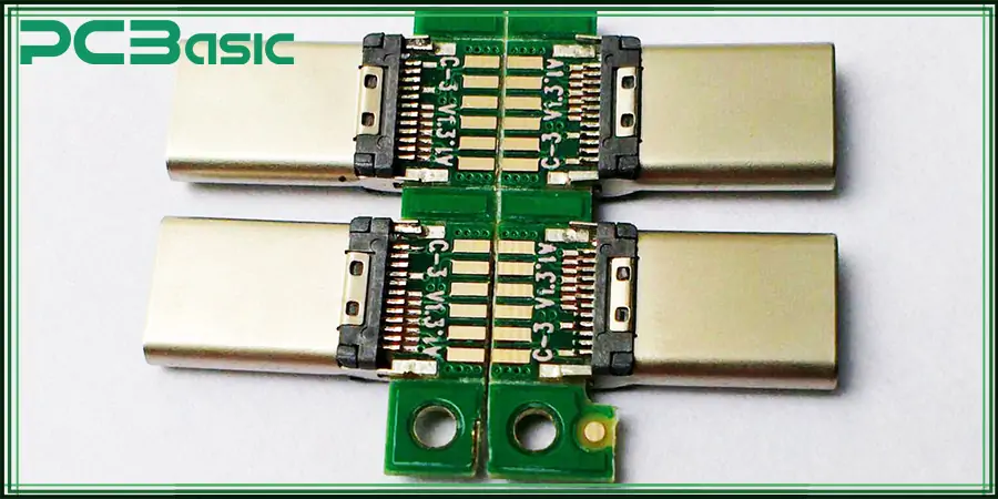
A USB circuit board is employed as a platform that ensures proper data transfer and power distribution. As an essential component in most of electronic devices, USB PCBs make sure charge transfers, data transfers, and even peripheral units.
They are intended to provide connectivity for different USB standards – such as USB 2.0, USB 3.0, and USB 4.0 – and various forms of connectors like PCB receptacles. Based on estimates, over 4 billion USB Type-C ports were shipped in 2023, implying the current high market demand for durable and diverse USB PCBs.
The USB PCBs can be categorized on the basis of core structure and design. Some of the common categories and their features are:
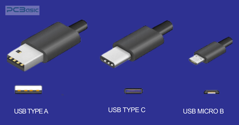
1. USB-A: The traditional connector with a rectangular form is adopted in keyboards, mice, and flash drives. Of course, it incorporates previous generations of USB, including USB 2.0 and USB 3.0. However, USB-A is even today more popular than its successors, and it is universally used in most desktop computers.
2. USB-B: USB-B connectors with a square shape are usually used in printers and most large devices. Although they are not frequently used in today's communication sector, they are still used in industrial applications where sound connectivity is needed.
3. Mini-USB: Also known as USB-B, but much smaller, Mini-USB was common in early portable devices and smartphones. It has been replaced predominantly with Micro-USB and USB-C connectors.
4. Micro-USB: Due to its size, it dominated the mobile devices market for years till such connectors were displaced by even smaller ones. It is compatible with USB 2.0 and 3.0 and has faster data transferring rates than the Mini-USB.
5. USB-C: The latest standard port connector is USB-C, which is highly flexible and can be inserted in either direction. It supports faster charging, better data speed, and other modes like video output. It has rapidly grown in the last five years, especially in smartphones and laptops, with over 55% of new device connections in 2023.
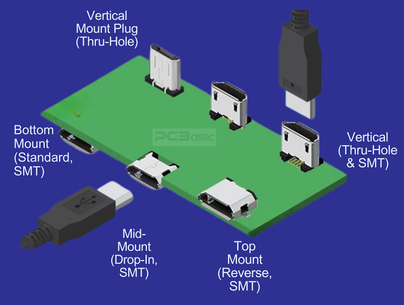
Vertical Through-Hole Connectors: With a 90° angle to the PCB, positioned connectors are a core element of industrial and automotive electronics. Due to their high reliability and durability, these connectors can bear a high mechanical load.
Top Mount Connectors: In this style, some connectors are soldered on the top of the PCB constantly in the production of electronic equipment. A top-mount USB PCB connector is very common in consumer electronics, including laptops, smartphones, and tablet products, for space-saving requirements.
Mid-Mount Connectors: These connectors are fitted into a hole in the PCB and then are secured in the middle. Mid-mount connectors enable the reduction of the general size of the device and are ideal for small and slim electronics such as portable media and small sensors.
Base-Mounted Connectors: Attached to the bottom side of the PCB, base-mounted connectors help in optimizing space. This type of production is common in multilayer PCBs where space is limited. Base-mount connects assist in getting the most out of space and is often incorporated in mobile phones and wearables.
Each type of USB PCB connector and mounting style serves specific applications, ensuring flexibility and efficiency across diverse industries. Proper selection of these components is vital to achieving the desired functionality and durability in USB PCB designs.
A small USB PCB is also composed of many components, next, I will introduce some USB PCB components for you:
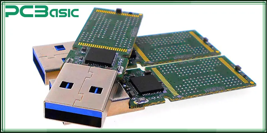
The USB PCB connector is the main interface for connecting USB devices to the host or other peripherals, and plays a key role in ensuring electrical contact and data transmission. For a USB PCB, the connector can be, for example, one of USB-A, USB-B, Micro-USB, or USB-C. When designing the USB layout, it is crucial to choose the right USB PCB connector (your device needs what kind of interface to match what kind of interface, otherwise it will not connect). In modern designs, USB C PCB connectors are increasingly used because of their reversibility, high-speed capability, and compact size.
The microcontroller (MCU) on the USB circuit board is the core of the USB PCB design. Why is it the core? Because the microcontroller handles the data and manages the communication between the USB host and the device (responsible for controlling the USB data transfer protocol and managing power requirements); USB differential pair data signals are also processed to ensure communication according to USB standards such as USB 2.0 impedance or USB 3.0 impedance. For example, in a USB hub PCB, the MCU ensures that multiple devices can connect and interact with each other.
The USB transceiver is an important component in the USB PCB and is responsible for converting the digital signal from the MCU into a USB data signal for transmission via differential pairs (D+ and D-). In USB PCB design, you must select a USB transceiver suitable for the USB version (such as USB 2.0 impedance or USB 3.0); Proper impedance matching is essential to maintain signal integrity and ensure reliable data transmission.
Resistors are used in various parts of the circuit in USB PCBs to control current flow and manage signal levels. The main types of resistors used in USB PCBs are pull-up resistors and pull-down resistors, which are used to set the correct voltage level on the USB data line. Be sure to choose the resistance carefully, so that the USB impedance can match, and the integrity of the signal on the data line can be optimal.
Capacitors in the USB circuit board mainly play the role of filtering noise and stabilizing power supply voltage. For example, decoupling capacitors (placed near a microcontroller or USB transceiver) are used to filter noise and smooth out voltage fluctuations, thus providing a stable USB signal. Large capacity capacitors on USB PCBs can also be used to support power needs, especially in USB hub PCB designs where multiple devices may consume power.
They produce the exact clocks needed for USB data to be synchronized. Crystal oscillators play the role of making sure that the data will not go through the wrong frequency.
USB devices specifically need well-steady voltages in order to function as expected. It regulates the voltage to ensure that the device receives the correct voltage levels because high or low voltage damages the device.
The ESD protection elements protect the PCB against damage from static electricity, which is of the essence to the durability of the USB devices.
USB Impedance Ensures Signal Integrity: Proper USB differential impedance is essential in PCB design to minimize signal loss and interference, ensuring reliable and high-speed data transmission across USB connections.
In addition to these components, USB PCBs of course have many other components. These components work together to ensure the overall functionality and reliability of the USB PCB. When it comes to USB layout, consider these elements carefully, as they are essential to ensure that the USB board meets the necessary performance standards, whether it is a USB c PCB, a USB hub PCB, or a traditional USB design.
Understanding USB 2.0 impedance is crucial for designing high-performance PCBs and ensuring reliable USB connections. USB PCBs offer several key benefits that make them essential for modern devices:
· Energy Efficiency: USB PCBs are energy efficient, which decreases the amount of power loss during data transmission and charging, thus increasing the duration of portable gadgets.
· Ease of Use: Since USB cable connectors are normalized, particularly the newer model, which is known as USB-C, using them is rather convenient for the consumer as no configuration is required.
· High-Speed Communication: The latest implementations in USB 3.0 and USB 4.0 make these PCBs efficient in providing capabilities for high transfer rates due to their high-speed applicability in projects like video processing and distribution, file sharing, etc.
· Compact Design: USB PCBs are relatively small in size, so they do not occupy as much room in various devices such as smartphones or IoT sensors.
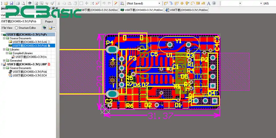
To create a USB PCB, it is necessary to consider several complex features for which it is crucial to guarantee the USB works as intended for an extended period.
· Signal Integrity: Signal integrity is paramount for the USB PCB since torque signaling may harm the data stream or reduce the rate of transfer. Control of the direction of routing and exclusion of other parts in the neighborhood aids greatly in signal integrity.
· EMI/EMC Compliance: USB devices should, therefore, follow the standards of electromagnetic interference (EMI) as well as electromagnetic compatibility (EMC) to ensure that the device does not interfere with other such devices. A combination of shielding and using the appropriate grounding can help control EMI.
· Thermal Management: USB ports and sometimes different USB devices may need to handle larger currents, for instance, while charging a phone or a tablet with some new fast charging technology or while transferring data at extra higher bit rates. Heat sinks, thermal connection, and correct positioning of electronic components ensure that the PCB does not get too hot and that its useful life is as long as possible.
· PCB Thickness: The thickness of the particular PCB greatly determines the strength and thermal characteristics of the complete PCB. The designers have to select an appropriate thickness to provide adequate protection to the device while maintaining its ability to dissipate the heat; all the while, the device cannot be allowed to become bulky.
Design of USB PCB boards can be a challenge, notwithstanding the fact that it is more of a software design than a hardware one.
· Hardware Issues: Bad signal routing and power supply can lead to data transfer disruption, signal integrity problems, or device failure, primarily when power is high.
· Software Problems: Incorrect values programmed in the software package mean that the data transfer rate can be configured to the wrong reading or even fail to connect to the host computer.
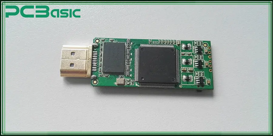
1. Optimize space and connections for compact designs: Since devices like USB are getting smaller and more portable, the available space is crucial. Optimization of the PCB space yields POP/PCB designs that are small, serviceable and high-performance, suitable for installation in small enclosures.
2. Use proper grounding and shielding techniques for signal integrity: The emergence of electromagnetic interference and proper signal quality thus requires the use of correct conductors and shielding. This decreases the level of interference on the signals and eliminates the possibility of data loss.
3. Ensure thermal management for power-intensive applications: USB cables that offer high-speed data transfer or fast charging creates more heat than other traditional cables. Other forms of thermal control include the use of thermal vias, heat sinks, and component spacing to prevent heat buildup and eventual heat stress.
1. Consumer Electronics: These PCBs are used on the following electronic devices: mobile phones, laptops, tablets, and gaming consoles. They can be easily charged, synchronized, connected with peripherals with no or little trouble and with reliable data transfer.
2. IoT Devices: USB PCB allows low-power, high-speed communication in IoT applications such as sensors, wearable electronics and home appliances. It also helps to enter large IoT Networks that are focused on reliable connections.
3. Automotive Electronics: In automobiles, USB PCBs find applications in Infotainment, charging ports, gadget connectors, etc. They support data transfer, diagnosis of cars and multimedia in connected automobiles.
4. 5G Networks: USB PCBs provide high-speed data transfer, which is characterized by the 5G networks. Connectivity interfaces of USB 3.0 & 4.0 provide an interface for routers, modems, & network equipment for efficient data transfer in 5G devices.
5. Medical Devices: These USB PCBs are found to be applicable to medical instruments such as glucose meters, monitors, and diagnostic instruments. The device ensures that information is transferred, charged, and communicated to the healthcare system for quality patient delivery.
Here are some essential tips to optimize your USB layout for performance and reliability:
1. USB 4.0 and Beyond: The emergence of USB 4.0 offers the promise of stepping up data transfer rates and power delivery specifications. With transmission speeds of up to 40Gbps, USB has been developed as a perfect solution for bandwidth-demanding applications such as 8K video streaming as well as gaming, and virtual reality. Future USB standards should further these already to make USB interfaces far from just a simple interface but far more sophisticated and at a far greater transfer rate than current standards.
2. USB Type-C Adoption: USB Type-C interfaces have found great demand because of their reversed use, high-speed data transfer capability together, and expanded power supply compatibility. This trend is likely to be on the rise as an increasing number of devices adopt Type-C for charging, data, and video transmission. Due to its compact size and compatibility, this technology can be applied to almost any class of devices, from laptops and mobile phones to game consoles and wearable electronics.
3. USB for IoT and 5G: Increasing the demand for swift data exchange, the use of USB integration for IoT devices and 5G networks will remain a trend. USB will be critical in linking 5G devices and ensuring the IoT sensors and smart devices are well connected with cloud solutions and other smart systems.
4. USB-C Alt Mode: USB-C Alt Mode enables USB Type-C connectors to also support other communication protocols, including Display Port and HDMI, in addition to USB data and charging. This capability is anticipated to grow by extending to even more new applications. The USB C will be the supreme universal connector in a single inker for client monitor video output, high-speed information, and power transmission, making the connection even more inescapable in future technology.
Therefore, USB PCB plays a significant role in modern electronics by allowing various critical functionalities in consumer electronics, IoT, automobiles, 5G communication technology, and the medical sector to be committed. Thus, their development, especially with USB 4.0 and Type-C GRE, has greatly only enhanced the prospects of data transfer rates and even power delivery.
With the rise in the demand for faster data transfer and communications, USB PCBs will remain central in defining the future of technology. A USB hub PCB integrates multiple USB ports on a single circuit board, enabling simultaneous connections and data transfer between multiple devices. They have a promising future ahead of them, and there is even the USB-C Alt Mode that increases their functionality even more.

Assembly Enquiry
Instant Quote
Phone contact

+86-755-27218592
In addition, we've prepared a Help Center. We recommend checking it before reaching out, as your question and its answer may already be clearly explained there.
Wechat Support

In addition, we've prepared a Help Center. We recommend checking it before reaching out, as your question and its answer may already be clearly explained there.
WhatsApp Support

In addition, we've prepared a Help Center. We recommend checking it before reaching out, as your question and its answer may already be clearly explained there.
