Global high-mix volume high-speed PCBA manufacturer
9:00 -18:00, Mon. - Fri. (GMT+8)
9:00 -12:00, Sat. (GMT+8)
(Except Chinese public holidays)
Global high-mix volume high-speed PCBA manufacturer
9:00 -18:00, Mon. - Fri. (GMT+8)
9:00 -12:00, Sat. (GMT+8)
(Except Chinese public holidays)
HomePage > Blog > Knowledge Base > Countersink Holes in PCBs
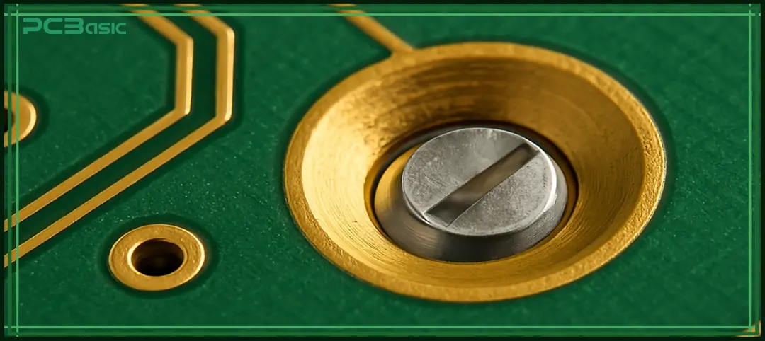
Every design parameter in a printed circuit board is crucial in determining the product's precision. One such crucial design parameter is the Countersink hole. Countersink holes become important when the designer needs to mount a component to a circuit board. The countersink is a conical hole that is used to mount the connectors on a PCB board. Countersink holes improve the mechanical stability and reliability of PCBs. The use of countersink holes in your PCB design enhances device performance, which contributes to the longer lifetime of the device.
This article enables you to understand the fundamentals of countersinks, their uses, and how one can add countersinks in their PCB design. Counterbores also look like the countersink, but they serve a unique purpose in the circuit board. Understanding the differences between them is essential for the designers to make informed decisions. At the end of this article, I will also introduce you to the basic differences between countersink holes and counterbore holes.

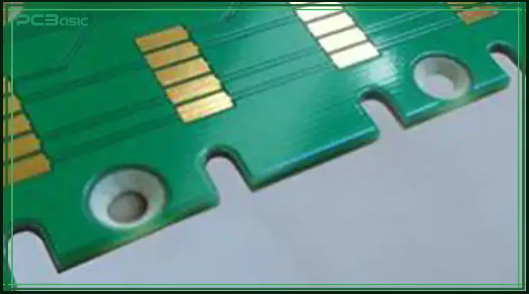
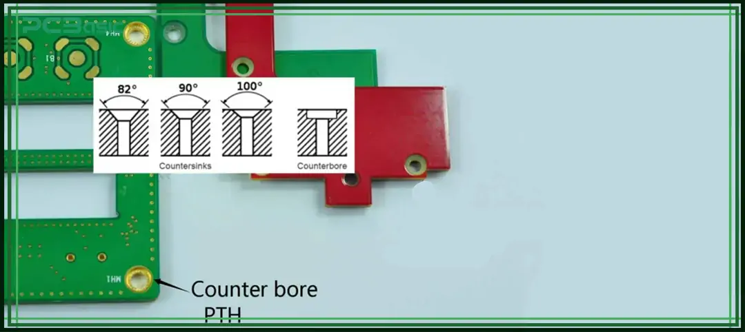
A countersink is a hole in a PCB surface that allows the screw to fit on a board surface. The countersink hole is of a conical shape that has a broader look compared to the hole itself. The countersink holes can be made with different angles like 82°, 90°, 100°, or 120°. The most common countersink hole angles are 82° and 90°. The countersink holes are either plated or non-plated. It is essential to note that countersink holes are mechanical features and distinct from PCB vias. The most common application of a countersink hole is the use of a countersunk bolt. The advantage of using the countersinks in PCBs is that it eliminates the burr left over after the drilling process.
Countersink holes are commonly used in circuit board design because they provide a smooth and even surface and prevent the screw from sticking out. This helps keep the PCB surface smooth and prevents screw heads from protruding. There are plenty of reasons why you should use countersinks in your PCB design.
1. Reduce Surface Collision: Space is a major concern in the PCB design of most applications, like defense and medical electronic devices. Countersink holes eliminate the bumpy terrain caused by fasteners, providing enough clearance between PCB boards that are stacked on each other.
2. Aesthetic Finishing: In most applications, aesthetics is important, like consumer electronics, smartphones, and other compact devices. Countersinking provides an aesthetic and clean appearance that makes the product attractive.
3. Better Mechanical Support: The countersinking helps uniformly distribute the force, resulting in improved mechanical support across the board and improving the alignment of screws.
4. Ease in System Enclosure: The countersink holes provide a smooth and polished surface as compared to other conventional screw holes. This helps the circuit board to easily fit within the product's mechanical body.

Countersinks in printed circuit boards are added using specialized tools and a comprehensive process, such as the drilling process, compliance with industry standards, and its impact on the board’s mechanical stability. This section will take you through the important steps of how countersink is added to your PCB design.
Step 1: PCB Design Phase
This is the first step towards adding the countersinks into the PCB design. In your specific PCB design software like Eagle or Altium Designer, define the countersink holes by properly including all the mechanical details of countersink holes (angle, depth, diameter). Also, include the details of the mechanical layer and drill symbols, i.e., plated or non-plated. In this step, you will also decide whether the countersink hole will be on one or both sides of the PCB. After the design finalization, Gerber files are generated for manufacturing to start the fabrication process.
Step 2: Material Considerations:
The material of PCB design is also an important parameter that must be considered before making any decision about the countersink hole. For instance, fiberglass and plastic-based PCBs have entirely different material properties. Therefore, the countersink design must also be chosen accordingly. The PCB design engineer may need to discuss the specific countersink hole design with the manufacturer to ensure it complies with the material properties.
Step 3: Countersink Hole (Size, Angle, Depth)
Before drilling the countersink hole in the PCB design, it is important to ensure that the countersink hole size and screw head size must exactly meet each other. The countersink hole size, angle, and depth must match with the screw head to ensure that it easily and accurately fits into its intended location.
Step 4: Fabrication Process
The Gerber files are sent to the PCB manufacturer. The countersink holes defined in your design are now physically drilled using the CNC machining. Generally, to drill a countersink hole, a specific drilling bit like a countersink bit (or conical drill bit) is used to add the countersink hole to ensure accuracy and precision.
Step 5: Surface Finishing
Although the countersink holes are known for their accuracy and precision, the CNC drilling process can leave burr that must be clean to avoid any aftermaths.
Step 6: Quality Assurance
Once the countersink holes are added to your PCB board. The different quality inspection equipment, such as Automated Optical Inspection, X-ray Inspection machines, and mechanical inspection tools, is used to ensure the countersink hole complies with all the quality standards and to identify any defects.
The countersink holes are used in the PCB design to achieve precision and accuracy. However, their design needs careful attention and consideration to achieve accuracy and precision. The following are some important design considerations for countersink holes.

Countersink Hole Size: The countersink holes can be made with different angles like 60°, 82°, 90°, 100°, 110°, or 120°. The angle of the countersink must be double-checked to ensure it fits exactly the screw head. The common way to calculate the depth of the countersink hole is given as follows:
Where D2 is the drilled hole diameter and D1 is the countersink diameter. The θ represents the angle of the countersink, e.g., 82°, 90°.
Suitable Clearance from Components: Another important design consideration while designing countersinks is to avoid placing the electronic components close to countersink holes. Placing components close to the countersink holes is dangerous as the drilling process can damage the component, resulting in device failure or degrading the PCB functionality.
Board Requirements: The thickness of the PCB board plays a vital role in accommodating the countersink holes. The overly thin or inappropriate selection of PCB board thickness can lead to mechanical instability or break the PCB board. This is because, if the board thickness is not compatible, the drilling process can damage the board.
There are commonly two types of techniques used for holes on PCB, known as countersink holes and counterbore holes. While both serve unique purposes, the understanding of differences between them is crucial for the engineers to make informed decisions.
|
Feature |
Countersink |
Counterbore |
|
The shape of the hole |
Countersink holes are commonly a conical shape |
Counterbore holes are commonly cylindrical |
|
Recommended angles |
82°, 90°,100°,are recommended in countersink holes |
Counterbore only allows 90°. These holes are flat-bottomed |
|
Screw Type |
Countersinks allow flat-head screws |
Counterbore allows the socket head screws |
|
Finishing |
Tapered finish for flush screw heads |
Flat-bottomed finish for socket head screws |
|
Applications |
Countersink holes are used in a wide range of applications, including circuit boards, woodworking, and hardware installations. |
Counterbore holes are mostly used in mechanical assemblies, such as aircraft assemblies and space applications. |
|
Material used |
Commonly, brass and aluminum are used |
Counterbore uses steel and aluminum. |
To sum up, the countersink holes are used in printed circuit boards to achieve accuracy and efficiency. The use of countersink holes in your circuit board not only provides precision but also gives an aesthetic look, which is important for many applications, including consumer electronics and automotive applications. Apart from that, countersinking in your design also provides mechanical stability and enough space clearance between PCB stacks. Understanding the countersink, its uses, and the difference between countersink and counterbore are important for PCB design and mechanical engineers to make informed decisions in their designs.

Assembly Enquiry
Instant Quote
Phone contact

+86-755-27218592
In addition, we've prepared a Help Center. We recommend checking it before reaching out, as your question and its answer may already be clearly explained there.
Wechat Support

In addition, we've prepared a Help Center. We recommend checking it before reaching out, as your question and its answer may already be clearly explained there.
WhatsApp Support

In addition, we've prepared a Help Center. We recommend checking it before reaching out, as your question and its answer may already be clearly explained there.
