Global high-mix volume high-speed PCBA manufacturer
9:00 -18:00, Mon. - Fri. (GMT+8)
9:00 -12:00, Sat. (GMT+8)
(Except Chinese public holidays)
Global high-mix volume high-speed PCBA manufacturer
9:00 -18:00, Mon. - Fri. (GMT+8)
9:00 -12:00, Sat. (GMT+8)
(Except Chinese public holidays)
HomePage > Blog > Knowledge Base > What is GND (Ground, Ground Wire) Meaning? Things You Need to Know

In the field of electronics, the term GND or ground is quite prominent. Every person who is involved in the activities of designing, constructing or maintaining circuits needs to know what GND means. It goes beyond a mechanistic view and translates into a concept that is crucial to the safety, efficiency, and operations of almost all present-day electronic tools.
GND is informally referred to as a ground or ground wire, which is known as an electrical circuit providing a joint return for electric current or a direct connection to the Earth. Satisfying the need to translate the concept of GND can prevent the possibility of circuit breakdowns. This improves the efficiency in operation and ensures the safety of both the devices and the users against electrocution.
This article will explain GND meaning in electronics, why it is important in circuits, various grounds and how to manage GND aspects in PCB design housings. For an engineer, a hobbyist or just somebody who wishes to learn about electronics, this guide will give you the information required to understand and appropriately use GND in your projects.
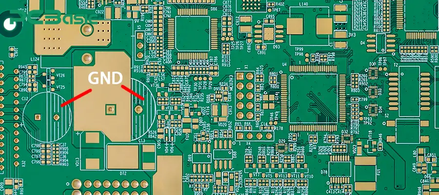
What is GND in electronics? The acronym GND is a term in electronics that stands for "ground". It provides a reference point in an electrical circuit concerning other voltages. In other words, GND is the voltage reference level against which other circuit voltage levels are measured. It is often used to close electrical circuits, allowing a current to exit.
In a broader sense, GND refers to any point in the circuit defined as zero volts. GND does not necessarily imply an Earth connection (though it most often does) but is an arbitrary level to which all other levels will relate.
 About PCBasic
Time is money in your projects – and PCBasic gets it. PCBasic is a PCB assembly company that delivers fast, flawless results every time. Our comprehensive PCB assembly services include expert engineering support at every step, ensuring top quality in every board. As a leading PCB assembly manufacturer, we provide a one-stop solution that streamlines your supply chain. Partner with our advanced PCB prototype factory for quick turnarounds and superior results you can trust.
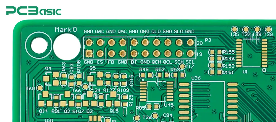
Ground is a word used in the circuit to mean a point of reference: zero volts. In other words, the voltage at this point is the reference for measuring all other voltages in the circuit. And that point, rather than being connected to the physical Earth, may just be a virtual point inside the circuit to which the current's return is made.
However, in other circuits involving alternating current supply, the ground is connected to the surface of the Earth so as to allow the undesired current to flow into the ground and avoid electrocuting any person touching the device. Further, in some other circuits, the digital ground may just be a similar point for the connection of parts, ensuring all the parts of the circuit are at the same voltage level.
There are several reasons why grounding is important in a circuit: it is a prerequisite for proper functioning, safety, and reliability of the entire circuit.
1. The first advantage of ground wire is that it provides support by creating a reference voltage point, which is usually set at zero volts. This reference point is rather crucial as all other voltages within the circuit in question will be measured relative to this voltage.
2. Most electronic components require a means of return path, which commonly referred to as the ground. The primary purpose of ground wire is to give stable ground to Electronics elements such as transistors, operational amplifiers, and integrated circuits. If it is missing, the components cannot do what they are supposed to, thus making the entire circuit useless.
3. As for security measures, grounding can only be considered replaceable or necessary. It provides a protective route for the fault currents, such as those generated by short circuits or insulation breakdowns, to flow directly to Earth.
4. Ground wire also offers the necessary protection to both electronic equipment and the users against risks such as electric shock or fire outbreaks. There are several types of grounds that come in handy in these difficult times.
In other words, grounding is required to hold the circuit steady, provide safety, keep the signals clear, and enable the two port devices.
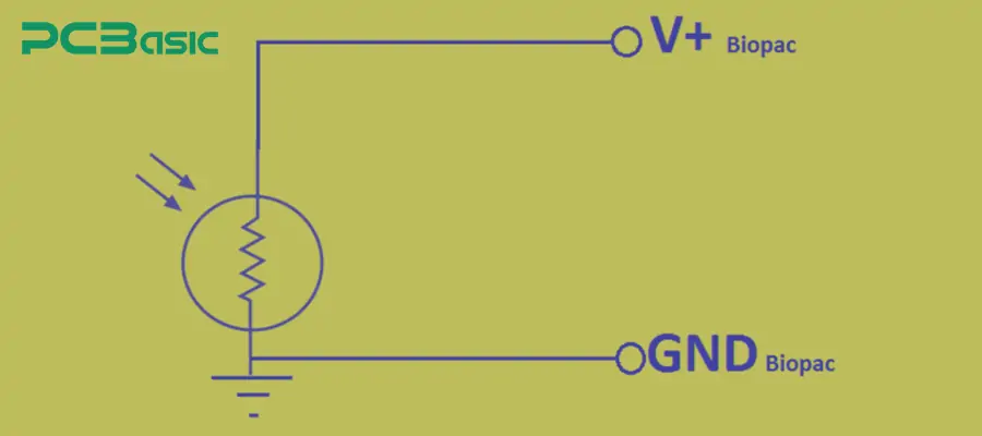
1. Providing a Reference Potential
The main reason for including a ground wire in an electrical circuit is to ensure that it serves as a reference point for all the voltages in that circuit. This reference is usually accepted as ordinary zero volts, and all the remaining voltages are a comparative measurement.
Creating such a reference line is also quite important in the functioning of electronic components, as it guarantees that voltage levels will be constant and predictable.
2. Protecting Circuit Safety
The ground wire serves its protective function; this is why ground is essential in a circuit. For instance, in a short circuit situation, the normal electrical path is through the ground wire, which is used to carry the fault current to flow to Earth. This prevents circuits from getting spoiled, subduing the chances of an electrical hazard to users. In the case of fault conditions, without a ground wire, the fault currents would follow unwanted paths, causing harm and destruction.
3. Completing the Current Path
The power source drives an electric current in any circuit. The current flows through a circuit’s components and returns to the power source again. Ground wire allows the current to flow by creating a return path for the current, completing the circuit. Without a ground wire, the circuit would be seen as open with no current flow.
4. Stabilizing Power Supply Voltage
The purpose of ground wire is to help stabilize the power supply voltage as it provides a common return path for the current. This is critical in circuits with several power units or complex high-voltage where the power supply varies.
Ground wire thus helps maintain the power supply voltage level. Surpassing the voltage peaks or falls can become detrimental for the components, resulting in a malfunction.
1. Signal Ground
Signal ground is also referred to as a low voltage ground that provides an electrical reference for signal or low voltage circuits of a given circuitry. Due to external influences, all other signals are referenced to the ground signal, helping to prevent voltage levels in the circuit from drifting in positive or negative directions.
Signal ground circuit remains isolated from other types of grounds, such as power ground, to avoid any noise from power supplies, which can deeply affect the signals.
2. Power Ground
The power ground acts as the reference point for the power supply voltage in a circuit. In most cases, it is connected to the negative pole of the power source where the current returns. Power ground wire is often connected to the physical Earth for safety purposes and to avoid fluctuation in voltage levels.
3. Digital Ground
Digital ground serves as a reference point for different levels of the digital signals in the digital circuits. It resembles the signal ground, except it is helpful for digital signals, which have relatively high frequency and are prone to interference. The Digital ground is commonly maintained apart from analog ground because the noise from digital signals can interfere with analog signals.
4. Earth Ground
Earth ground means a connection to the Earth through some medium. Fault currents enable the charge to flow safely, preventing electric shocks to a person and damage to equipment. Earth ground connects to the metal body of the equipment for carrying the fault currents to the ground in case of a short circuit or any other faults.

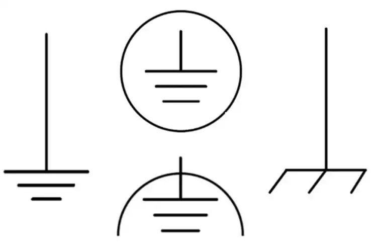
The green or black wire is a grounded circuit. The ground wire in the circuit diagram is usually represented by this symbol or one of the other regulated ones. Most of the circuit diagrams include the following symbols Ground:
Earth Ground Symbol: It is represented by the combination of three sequential horizontal bars, demonstrating a decreasing trend in their length from top to bottom. It is used to denote a direct contact with the Earth and is found in circuits with a high safety requirement.
Chassis Ground Symbol: This symbol also appears as a set of three positive parallel lines, with the last or bottom line being the longest and the top two being of equal size. It is used to indicate their attachment to the metal casing of a device and is common in automotive and industrial circuitry.
Signal Ground Symbol: This symbol is a downward upward triangle with inductive circuitry, often incorporated in electronics, to show a connection point that is meant to be a reference level for other signals.
Ground Symbol: This symbol is more like a signal ground symbol but is more often used in digital circuit drawings as a synonym for reference ground for digital circuitry.
In relation to these symbols, the truth remains that they are significant in both reading and designing circuit diagrams since they will always tell where the ground connections are made and what kind of ground is being employed in these instances.
The ground wire works on the principle that electric current will always follow a path of least resistance. The circuit will provide a low-resistance route for the current to return to its power source or into the Earth if there’s a fault. Such a setup will definitely ensure safe operations and reliable equipment performance.
When the circuit is energized, the current flows from the power source through the components of the circuit, and it goes back to the power source via the ground wire. The purpose of the ground wire is to offer a secure path for fault currents to pass in case of faults, such as short circuits and loose connections. That is why ground is important in a circuit, as it protects the circuit from damage and reduces an electric shock hazard.
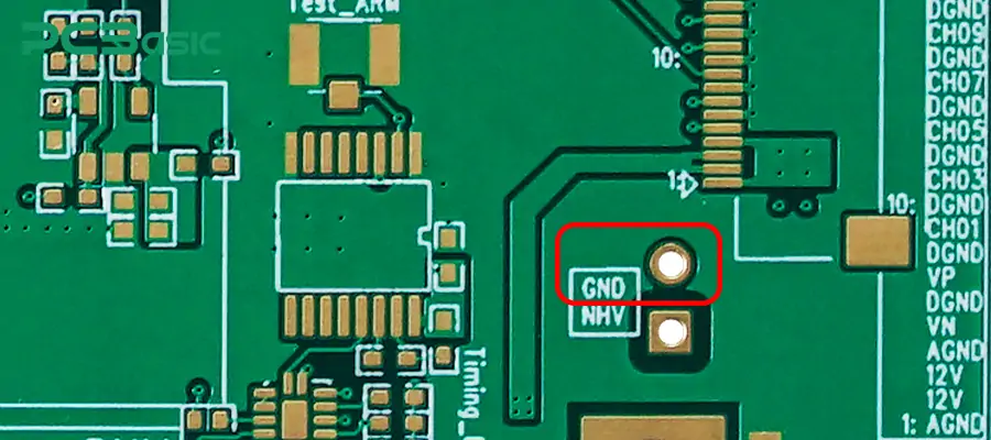
1. Power and Ground Layout
Power and ground trace layout is the most critical part in PCB design to ensure the performance and reliability of circuit. A good layout would help minimize noise, voltage drop, and interference between different circuit parts. This is necessary for a number of things: it has to keep power and ground traces as short as possible and route them in parallel to reduce loop area—effectively, to reduce electromagnetic interference.
2. Partitioning Layout
Breaking the PCB layout into well-defined areas of power, ground, and signals will minimize noise while improving performance. The digital and analog grounds are the types of ground that must be kept separate to prevent any noise from interfering with each other. To avoid interference, the circuit's high-power and low-power parts must be kept separate.
3. Thermal Management
When designing a PCB, it is essential to give careful thought to thermal management, particularly for high-power circuits. The ground planes can be very helpful and can have their function in dissipating the heat to protect components against overheating. By increasing the area of the ground plane with extra thermal vias, efficient transfer of heat away from hot components greatly improves circuit reliability and longevity.
4. Decoupling Capacitors
Decoupling capacitors are placed in circuits to filter out most of the noise and stabilize the power supply voltage. Place this component directly next to power pins on other components, with connections going straight to the ground plane. The components experience significantly reduced voltage spikes and noise when it (the power source) provides stable power.
5. Avoid Signal Line Crossings
Crossing signal lines over the power or ground planes can produce noise and interfere with the flow of the circuit. The signal trace should be routed in such a way that it crosses the least number of traces and keeps the maximum distance from power and ground traces. This rule is very critical in high-frequency circuits where even millisecond quantities of noise may affect performance badly.
One really needs to get a good partner in PCB design for one's project to succeed. The major service entities in PCB design and manufacture include PCBasic, which offers an extended range of solutions that meet demands of customers, engineers, designers, and hobbyists.
PCBasic focuses on high-quality PCB fabrication, assembly, and testing services based on precision and reliability. The experience and resources that ensure success are at the heart of PCBasic, be it a very simple prototype or a complex production run.
In summary, what is GND in electronics? GND is not just a simple connection point in a circuit; it is the foundation upon which the entire circuit operates. By understanding the role of ground in electronics, you can design safer, more reliable, and more efficient circuits that meet the demands of modern technology.

Assembly Enquiry
Instant Quote
Phone contact

+86-755-27218592
In addition, we've prepared a Help Center. We recommend checking it before reaching out, as your question and its answer may already be clearly explained there.
Wechat Support

In addition, we've prepared a Help Center. We recommend checking it before reaching out, as your question and its answer may already be clearly explained there.
WhatsApp Support

In addition, we've prepared a Help Center. We recommend checking it before reaching out, as your question and its answer may already be clearly explained there.
