Global high-mix volume high-speed PCBA manufacturer
9:00 -18:00, Mon. - Fri. (GMT+8)
9:00 -12:00, Sat. (GMT+8)
(Except Chinese public holidays)
Global high-mix volume high-speed PCBA manufacturer
9:00 -18:00, Mon. - Fri. (GMT+8)
9:00 -12:00, Sat. (GMT+8)
(Except Chinese public holidays)
HomePage > Blog > Knowledge Base > What is the DC voltage symbol | A Comprehensive Guide?

DC voltage powers the electronic equipment that we use on a daily basis. It consistently transfers current in a single direction. The Unicode character "⎓" or a straight line represent DC voltage. DC voltage is an essential part of the power supply for modern electronics because of its steady, one-way flow. Whereas AC voltage regularly varies, DC voltage remains constant. On measuring equipment, DC voltage is easily identified by its distinctive "V" symbol with a dotted line above it. From solar cells to batteries and electronic devices, this reliable power source is essential to power systems of all kinds.
Let's examine DC voltage symbols, their practical applications, and the appropriate methods for measuring them using various instruments. Knowing this will enable you to comprehend how these symbols are used.
DC voltage creates electrical capacity with a constant polarity that pushes electrical charges to flow in one direction. This stable current helps separate it from AC voltage, which regularly changes direction and polarity.
Sometimes, questions arrive in mind: what does DC mean in text? So, "DC" letters in voltage mean "DC" or "continuous polarity", suggesting that the electrical charge continuously flows from positive to negative terminals in the same direction. The DC voltage maintains continuous polarity, although the size may remain stable (continuous Dick voltage) or can be changed over time (variable Dick voltage).
Common sources of DC voltage include:
● Battery and cells (chemical energy formation)
● Solar Panel (photovoltaic conversion)
● DC generator
● Improved power supply

We can’t measure the DC Power directly as there is no Power Symbol in Multimeter symbols to get the DC Power we measure the DC Voltage and DC Current and then calculate using the formula. DC power measures the electrical work performed in a given period. The formula to calculate it is: in watts (W)
Power (P) = Voltage (V) × Current (I)
This relationship indicates that neither voltage nor current determines the power alone - they work together. A circuit with high voltage and low current can spread the same power as one with low voltage and high current.
DC voltage and power have many great advantages. DC voltage can be stored in batteries, capacitors, and other devices. The supply of direct current provides stable, regulated output voltage that works well with sensitive electronic components. These features make DC voltage particularly valuable when you have portable electronics such as laptops and mobile phones.
While the alternating current remains standard for domestic electrical systems, most electronic devices use direct current. This requires the conversion of AC to DC voltage via rectifiers and filters to create regulated DC voltage. The computer and the TV require power adapters for this reason.
Engineers measure DC voltage. These devices provide accurate readings but can miss the fast voltage sortal called "Ripples" which can lead to DC voltage by replacing regulators. Engineers use this law in real-world applications to determine current, resistance, and voltage conditions in the circuit.
 About PCBasic
Time is money in your projects – and PCBasic gets it. PCBasic is a PCB assembly company that delivers fast, flawless results every time. Our comprehensive PCB assembly services include expert engineering support at every step, ensuring top quality in every board. As a leading PCB assembly manufacturer, we provide a one-stop solution that streamlines your supply chain. Partner with our advanced PCB prototype factory for quick turnarounds and superior results you can trust.
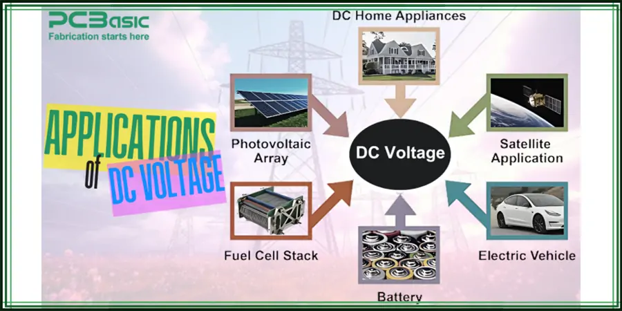
DC voltage transfers our world to mass industrial systems from the smallest electronic things. The stable current when it comes to stability and reliability makes it irreparable. Modern buildings require DC power to drive more than 70% of their devices. Your laptops, smartphones, flashlights, and battery-perception things are all run on DC Power. You can save up to 20% of energy by using direct DC power for DC waste for DC conversion.
DC voltage systems are the backbone of the automotive industry. Most motorways use 12V systems, while diesel-operated trucks and farm equipment work with 24V systems. Electric Vehicles (EV) use two DC systems, a 12V system for important tasks and a high voltage 300-400V system that provides strength to the main engines.
The telecom world runs on DC Power. Telephone exchange equipment usually uses a 48V DC power supply. This setup helps maintain telephone lines and communication networks with better backup options. Data centers have become the main users of DC voltage. Switching from AC to DC helps the owners cut cooling costs and run the backup system better. This improvement means something because data centers use about 4% of the world's current.
DC voltage makes production more accurate and efficient. DC motors provide better control than their AC colleagues. Mercedes-Benz saved energy by connecting its aluminum welding robots to the DC grid. Renewable energy fits naturally with a voltage. Solar panels make DC power directly. Wind turbines and other green energy sources also produce DC power that enters the battery without direct conversion. This makes the key to DC voltage for the development of green energy.
Hospitals rely on the DC power system so that important equipment can be run during the power outage. Many commercial buildings now use DC Power Distribution to support LED lighting, HVAC systems, and EV charging stations.
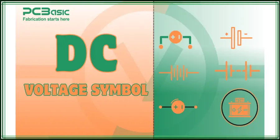
Electrical symbols act as a universal language that represents DC voltage in circuits and diagrams. Engineers and technicians can communicate in language barriers with these symbols. The standardized DC voltage symbol comes into different forms based on the reference.
Official Unicode character. Many electronic devices use this symbol to display direct current input or output. The International Electrical Commission (IEC) Standard IEC 60417 made this symbol official. This assessment is displayed on the plates and identifies the relevant terminal. U +2393 represents “⎓” (equality).
Circuit diagrams show DC voltage sources in several ways:
1. Battery Symbol - Parallel lines of different lengths make up the most common representation. The longer line shows the positive terminal while the shorter one marks the negative terminal. Series cells in the battery appear as multiple line pairs.
2. DC Source Symbol - A circle with plus and minus signs shows the polarity direction. Some diagrams use a simple straight line instead.
Engineers add a diagonal arrow pointing to the north-east through the standard symbol to display DC power supply.
Measuring equipment and multimeter show DC voltage by specific methods. A dotted line with a solid line over the "V" marks the DC voltage. Some devices only show "DC" or use a horizontal line. The AC voltage appears as an "AC" or a wavy sign wave line.
The polarity of the DC voltage symbol plays an important role in showing the current flow direction. Positive Divide voltage means that the charge flows from the charging to negative electrodes. Negative DC voltage reflects the opposite path.
The voltage (V) in technical documents represents the potential energy of the power supply stored in the form of charge. The tension between the two circuit points forms a "potential difference" or "voltage drop".
Electrically scheduled reading and measurement units require a solid understanding of these symbols. Standard DC voltage symbols help prevent errors in circuit design and construction. They enable clear technical communication between electrical engineers around the world.
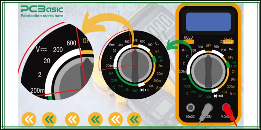
Digital multimeters will give a perfect way to measure DC voltage accurately and safely. The symbols for DC voltage differ from complex circuit diagrams. These devices use specific notations that indicate voltage settings and readings.
In most of the Multimeters, the DC voltage symbol on the multimeter is display as a V with a straight line above it or V⎓ above the ohms symbol which is also one of the multimeter symbols. You'll find some displays showing a V with one dotted line and one solid line above it just after the ohms symbol to distinguish it from AC voltage's wavy line. DCV or similar abbreviations appear commonly on older models.
Your multimeter will give accurate DC voltage readings with the proper setup:
1. Turn the selector dial to the DC voltage position
2. Select the DC voltage option on auto-ranging multimeters
3. Manual-ranging models need the highest voltage setting first, then adjusted downward
Accurate readings depend on proper probe connections present behind the multimeter symbols. The black probe goes into the COM (common) port while the red probe connects to the port marked V, VΩmA, or with the voltage symbol. Many users mistakenly insert probes into amperage ports instead of voltage ports.
Test probe placement significantly affects your readings. DC flows in one direction, so each component has positive and negative ends. The red probe belongs on the positive terminal and the black on the negative. Your readings show negative voltage. Just swap the probe positions.
The right voltage range matters to accuracy. A 12V battery measurement needs the 20V setting. The 2V range measures up to 2 volts, while 20V handles up to 20 volts. High ranges reduce accuracy, and low ranges trigger an "OL" (Over Limit) display.
Your multimeter screen displays measurements with a DC V symbol that indicates direct current voltage symbol. Digital multimeters show exact numerical values, unlike analog meters where you read the needle's position on the scale.
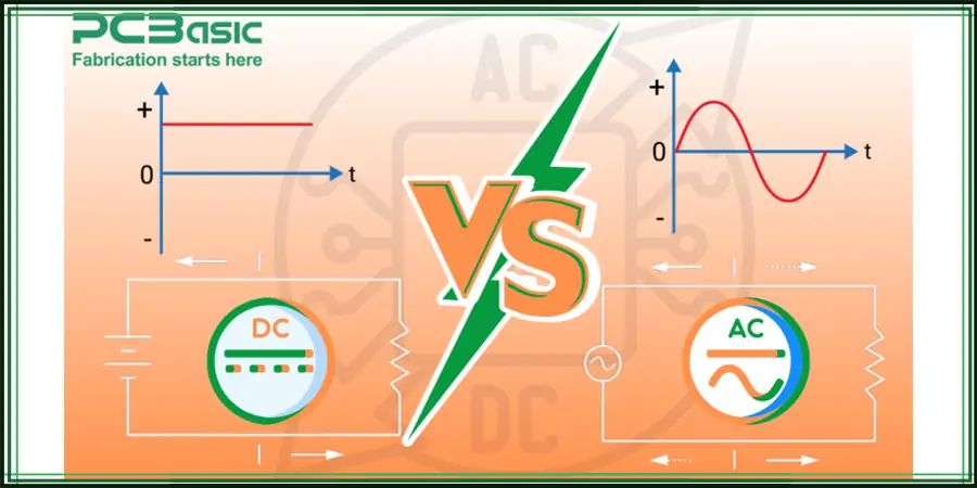
The basic differences between DC and AC voltage explain why each type of electrical power uses specific symbols.
The main difference between DC ((direct current)) and AC (Alternating current) lies in their electric current direction. The electricity of DC voltage continuously flows in one direction from positive to negative terminals similar to the flow of a river. The AC voltage changes direction from time to time and forms a sinus-shaped wave that is optional between positive and negative.
These patterns become clear on graphs. If we look at DC vs. AC Voltage symbol then, DC voltage shows up as a flat line, while AC voltage creates a wave-like pattern. Their symbols reflect these characteristics - DC voltage uses a straight-line symbol (⎓), and AC uses a wavy line (~).
DC voltage has zero frequency because its direction remains constant. AC voltage operates at 50-60 Hz based on regional standards, which means it switches direction 50-60 times each second.
Each voltage type serves unique purposes based on their properties:
DC Voltage Advantages:
● Delivers stable power that electronic devices need
● Storage capability in batteries and capacitors
● No reactive power losses
● Better fit for smaller consumer electronics
AC Voltage Advantages:
● Easy voltage level transformation using transformers
● Higher efficiency in long-distance transmission
● Safe interruption due to periodic zero-voltage points
● Standard power systems in households
Most electronic devices like computers, phones, and televisions need DC voltage internally despite their AC power connections. Power adapters on device cords contain bulky blocks that convert household AC to DC through rectifiers.
Knowledge of these differences is vital for anyone working with electrical systems, especially while reading circuit diagrams where specific symbols represent each voltage source.
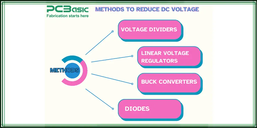
You need to choose between efficiency and simplicity when reducing DC voltage. Several methods exist based on your needs and technical limits.
Voltage dividers are the quickest way to reduce DC voltage. Two resistors in series let you pick off voltage at their junction point. Similar value resistors will get you half the input voltage. To get a quarter of the voltage, make the top resistor three times bigger than the bottom one. Despite that, current flows through the resistors straight to the ground and wastes power. This makes it a poor choice for battery-powered devices.
Linear voltage regulators are one of the method to reduce the DC voltage to give you more stable output voltage reduction. Popular options include adjustable regulators and fixed-output options like the 7805. These parts keep steady output whatever the load changes. They turn excess voltage into heat, which isn't great when there's a big gap between input and output voltage.
Buck converters (step-down converters) are the most efficient option. These switching regulators use inductors and capacitors to convert high voltage to low voltage while losing minimal energy. They're trickier to set up at first but ended up saving battery life and generating less heat. This allows for smaller device designs.
Diodes in series can work for tiny voltage drops in specific cases. Silicon diodes drop voltage by about 0.7V, while Schottky diodes drop around 0.3V. This simple approach works well for low-current uses but won't give you precise regulation.
Here's what to think about when picking a voltage reduction method:
● Current needs (milliamps vs. amps)
● Battery life importance
● Heat management ability
● How precise regulation needs to be
● Space constraints
Modern electronic devices mostly use buck converters because they work better. They're especially useful when powering parts that pull much current from batteries or limited power sources.
Boost converters offer a powerful solution in electronic designs that need higher DC voltage levels. These specialized DC-to-DC converters increase voltage and decrease current at the same time, which keeps overall power conservation intact.
Step-up converters (also called boost converters) work through a quick and efficient energy transfer process. The process starts as energy gets stored in an inductor when the electronic switch closes. The stored energy moves through a diode to the load once the switch opens. This simple two-stage operation lets voltage increase by changing the duty cycle.
The input and output voltage follow this formula:
Vout = Vin / (1-D)
D stands for the duty cycle - the time percentage when the switch stays on. Output voltage rises sharply as the duty cycle gets closer to 1 in theory. However real circuits with duty cycles above 90% might see a voltage drop because of component limits.
Boost converters shine with their remarkable efficiency. Some designs can reach. Almost all input energy turns into useful output energy with minimal loss. Battery-powered devices benefit greatly from this efficiency since they need to save every bit of energy up to 99% efficiency.
Step-up conversion powers many real-life applications. The Toyota Prius uses boost converters to raise battery voltage. This is a big deal as it means that the required battery cells drop from 417 to just 168. White LED lamps running on 1.5V alkaline cells also need boost converters to reach their required 3.3V for light emission.
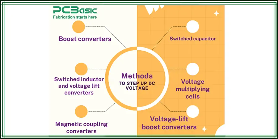
These alternative step-up techniques exist beyond standard boost converters:
● Switched capacitor (charge pumps)
● Switched inductor and voltage lift
● Magnetic coupling
● Voltage multiplying cells
Solar photovoltaic systems use special voltage-lift boost converters to improve power quality and system performance. These converters extend traditional boost design by adding strategic passive components like diodes, inductors, and capacitors. Electromagnetic emissions remain the biggest problem with boost converters. Designers must add proper filtering solutions to address this issue.

Assembly Enquiry
Instant Quote
Phone contact

+86-755-27218592
In addition, we've prepared a Help Center. We recommend checking it before reaching out, as your question and its answer may already be clearly explained there.
Wechat Support

In addition, we've prepared a Help Center. We recommend checking it before reaching out, as your question and its answer may already be clearly explained there.
WhatsApp Support

In addition, we've prepared a Help Center. We recommend checking it before reaching out, as your question and its answer may already be clearly explained there.
