Global high-mix volume high-speed PCBA manufacturer
9:00 -18:00, Mon. - Fri. (GMT+8)
9:00 -12:00, Sat. (GMT+8)
(Except Chinese public holidays)
Global high-mix volume high-speed PCBA manufacturer
9:00 -18:00, Mon. - Fri. (GMT+8)
9:00 -12:00, Sat. (GMT+8)
(Except Chinese public holidays)
HomePage > Blog > Knowledge Base > PCB Mounting Methods| Your Ultimate Guideline to PCB Assembly!
PCB mounting methods aid in assembling the board. Crews, clips, and parts are utilized in the process. Two methods are described in turn in lay terms. Both of them contribute to building solid boards.
This blog demonstrates how to do this. The purpose is to enable the client to understand the proper way. That is what we are going to discuss here.
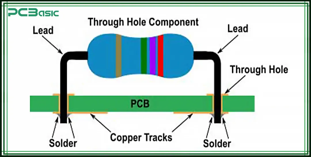
The through-hole PCB mounting method entails utilizing small holes in the PCB. These holes are meant to accommodate components such as resistors and capacitors. A 0.8mm thick cast iron piece will be drilled using an 8mm drill bit to create the holes.
The leads from the components are bent in such a manner to ensure that they do not come off easily. These are then soldered on the other side. The connections can handle up to 3A, which is perfect for strong currents. This method also employs resistors with a tolerance of ± 5%. The spacing between the pins is 2.54mm, making it fit standard PCBs.
PCB mounting methods like this are very stable. They grip parts firmly and also work well when there is a lot of vibration, for instance, in automobiles. It does; that is why it is so popular for car electronics brands to use them. Parts are easy to replace, which is beneficial in repairing objects.
Soldering cannot exceed 260°C in order to avoid damaging the CPU or GPU of the laptop. It prevents the copper that is present on the PCB from floating up. Even ICs such as 555 timers can also be inserted this way. First, an elimination-type heat sink is incorporated for hot parts.
Through-hole circuit board mounting methods may be combined with SMT. Both are used where space and performance require special circuits, which are important. They can have a rating of 16V to ensure that they are safe to operate in low-voltage circuits. The standard lead diameter is 0.5mm.
All connection points – or solder joints – must be visually inspected to guarantee sound. A loose joint is not advantageous and may instigate difficulties in the future. This method is powerful, simple, and the best to use in many electronic projects.
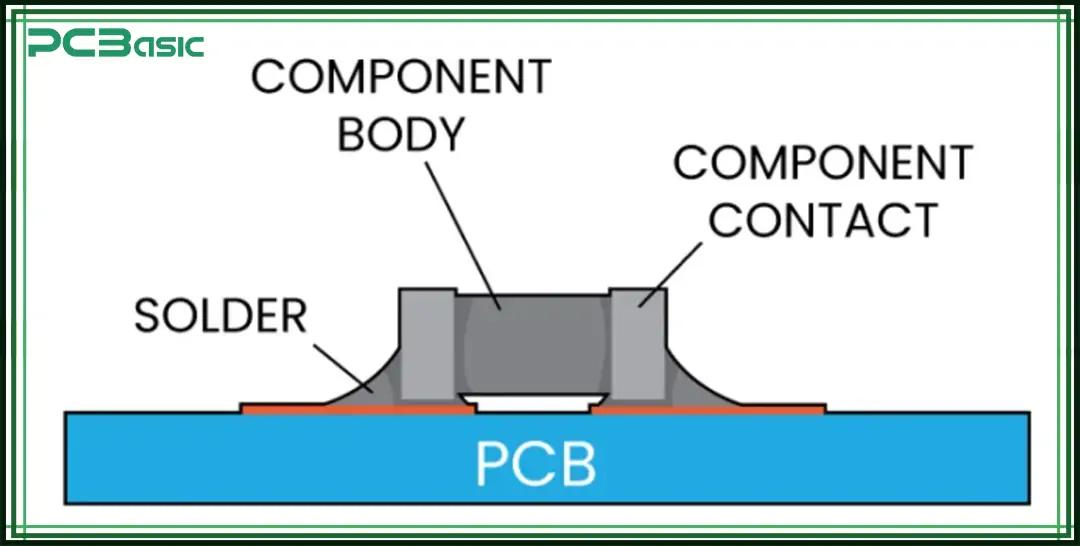
SMT, or Surface-Mounted Technology, can be defined as a method of producing electronic circuits; the components are mounted directly onto the surface of the PCB. Individual components such as resistors, ICs, and others are mounted on the surface of the PCB. Mounting circuit boards such as this one employ a special paste that is composed of small metal particles.
SMD components such as the 0402 resistors (1.0 mm × 0.5 mm) are placed at their appropriate locations by machines known as pick-and-place robots. Then, everything gets hot, up to 250°C, to make the parts stick. It is different from its precursors in the sense that it doesn't require holes.
SMT is excellent for new technologies. It is a fact that various techniques for mounting PCBs using SMT can improve the functionality of phones and computers. Components such as BGAs and QFPs can be found here. As shown above, it is relatively small, its size is only 10 µm wide, and it can fit into this circuit design.
Quality checks are performed by AOI systems, and cameras are used to detect errors. The knives guarantee the examination of concealed areas through X-ray machines. This method is ultra-meticulous, with the pieces positioned with a precision of 10 microns.
They also use stencils where they put printing paste on boards just to be accurate to 0.005 inches. SMT is filled with tiny elements, such as 1005 chip resistors with a size of 0.4 mm × 0.2 mm.
How to mount PCB parts correctly is crucial for stability. If a part requires repair, use hot air or special tools, the board will not suffer any damage. SMT enables the production of small, cool, and powerful electronics.

Mixed Technology combines two techniques of joining parts to boards. It employs both Surface-Mount Technology (SMT) and Through-Hole Technology (THT).
While some components are mounted through holes, such as 470µF capacitors, others are surface mounted, as is the case with the 0603 resistors measuring 1.6 mm x 0.8 mm. Techniques like PCB mounting allow engineers to choose where to install each device.
We can now say that these PCB mounting methods are both strong and smart. Big 5W resistors remain protected by THT, whereas small chips afford SMT. First, robots put SMT parts.
Next, people attach THT parts. The board gets heated twice: for SMT: 240°C for solder paste and 260°C for leaded components through the use of soldering iron, and for THT 260°C. Thus, each part adheres well.
Careful checking is important. AOI systems inspect SMT parts. X-rays check hidden parts. THT parts can be tested either by machines or by personnel. This ensures that all functions are optimized and operating as efficiently and effectively as possible. Mounting circuit boards correctly is vital to this process.
Mixed technology produces sharp, well-cool boards. For instance, a 12-layer board can accommodate big transformers with THT and small diodes with SMT. It is helpful in every part of doing the job that is best suited to it. Circuit board mounting must be precise for optimal performance.
Direct-Bonded Chip (DBC) bonds parts onto rigid ceramic substrates. It has 96% Al₂O₃ support while working with copper traces on it. Of the two layers, the copper is 300 µm thin, while the ceramic layer is 625µm thin. DBC operates at 1065°C, and the current density is 10⁴ A/m².
It cools very effectively here as thermal resistance is recorded at 0.1°C/W. It operates at a high voltage of 2500V and is durable for up to 10 cycles of power cycling. Techniques such as PCB Mounting Methods provide devices with 1200V/100A power. It makes them sturdy and robust.
Chip-On-Board (COB) mounts tiny chips directly onto thin 150 µm thick FR4 substrates. They use wires that are only 25µms wide and 4mm in length to make a connection. The wires connect to each other with an adhesive that cures at the temperature of 175°C in 20 minutes.
According to the COB concept, space usage is 50% less than in other arrangements, making it suitable for compact accessories such as LEDs. Modes of mounting circuit boards include COB, which fits 256 chips in one module. It allows the devices to remain cool with a maximum thermal rating of 5W/cm². That is why it is convenient to use COB in phones.
In Flip-Chip Technology, chips are flipped to join them with the help of boards. Despite its small size, it has features like tiny hills 80µm wide to enable connections. These bumps enable very high signal speeds of up to 10 GHz. They stick on at 220°C to form firm connections.
But to be more specific, there is a special glue that Flip-Chip uses to fill in all the gaps and make it more rigid. The chips remain cool with a thermal resistance of only 0.2°C/W. PCB mounting techniques such as the Flip-Chip are beneficial to quick computers as they improve their speed by 20%. These methods make them very compact.
Embedded Components tend to bury small parts within 1.5 millimeters-thick panels. These parts can be as small as 0402, with values from 10nH to 100µF. They are located in layers and are shielded with epoxy resin. This means the board is 40% reduced in size.
Methods of PCB mounting that involve embedding of parts ensure that signals are not interfered with by other connections. It has a working power of up to 5 W/cm² working power; it has 500 parts in one board. Of course, that makes these boards ideal for fast and sophisticated devices.
 About PCBasic
Time is money in your projects – and PCBasic gets it. PCBasic is a PCB assembly company that delivers fast, flawless results every time. Our comprehensive PCB assembly services include expert engineering support at every step, ensuring top quality in every board. As a leading PCB assembly manufacturer, we provide a one-stop solution that streamlines your supply chain. Partner with our advanced PCB prototype factory for quick turnarounds and superior results you can trust.
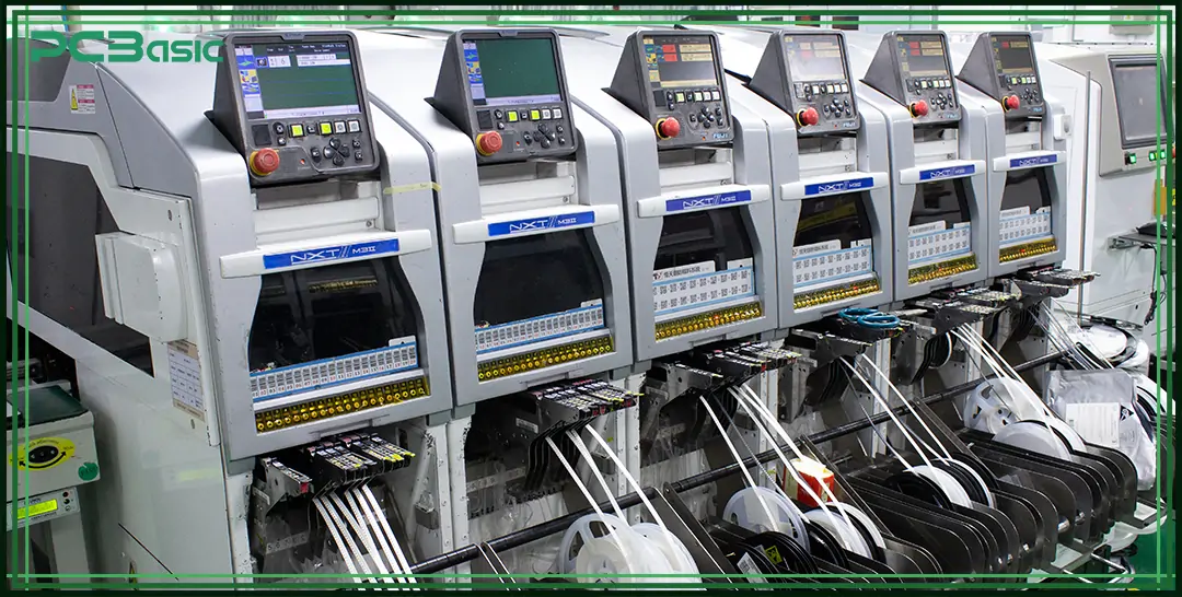
Pick-and-Place Machines assist in placing small parts on boards. Some of the things they select include resistors, capacitors, integrated circuits, etc. PCBasic JS Technology Co., Ltd. machines are fast, handling up to 50,000 parts per hour with great accuracy.
A vacuum nozzle is used in Europe to collect small parts, such as 0201-size chips and 0402-size resistors. They are then placed on the board with an accuracy of ±0.03 mm. The machine incorporates SMD feeders to feed parts.
Our company uses advanced Pick-and-Place machines to ensure high-quality and fast PCB assembly. It employs a technique of Part Placement by utilizing the PCB Mounting Method to orient parts at the 45° or 90° orientation.
For example, it can pick 50,000 parts per hour. In terms of the XY table, it is capable of moving with an accuracy of within 10 μm. They also ensure that there are no mistakes when using vision systems. PCB mounting methods are used to place the part on the boards that can be in sizes 100 mm x 150 mm to 500 mm x 500 mm, and the setup allows one to build it without errors.
It is selecting between various machines. Some machines employ linear motors for fast movements, which are suitable for producing many boards. This method is helpful with multiple designs, and it helps to maintain the boards to be effective. It tells where parts go using numbers and angles on the screen. It employs servo motors for fast movements.
They tally the quantities and detect abnormalities. Complex equipment also affirms that all parts fit quickly and without errors. This machine makes good boards, thus facilitating the execution of worker's tasks effectively and efficiently.
Solder Paste Printers are helpful in placing small components on a printed circuit board. They employ a blade that makes moves at a rate of 35mm per second. It is to be used on a stencil that has a thickness of 0.1mm. The precision of this tool is very high: ±12µm.
It places the paste in small holes and equally ensures that each of the holes is appropriately filled with the paste. Our Solder Paste Printers enhance the precision and speed of our PCB assembly process.
Another feature of the PCB mounting method is that paste is a tin-silver-copper alloy containing 96.5% tin, 3.0% silver, and 0.5% copper in terms of strength. Following spreading, the PCB is shifted on a conveyor at 120 mm/sec. This helps all processes to be done quickly.
They ensure positioning conforms with their intended position through the aid of a vision system that has a vision accuracy of 0.1mm/pixel. In this PCB mounting method, boards are of sizes up to 510mm x 460mm. The thickness of the board varies between 0.5mm and 1.6mm, while the height of the paste is between 0.15mm and 0.2mm. The printer works in a room whose environment is at 25°C.
Thus, the movement of the squeegee is at a 45° angle to the stencil. It prints and then cleans the stencil on its own after completing the process. The pressure sensors, thereby, balance everything, even to a variation of ±1%. This ensures that the job is done correctly.
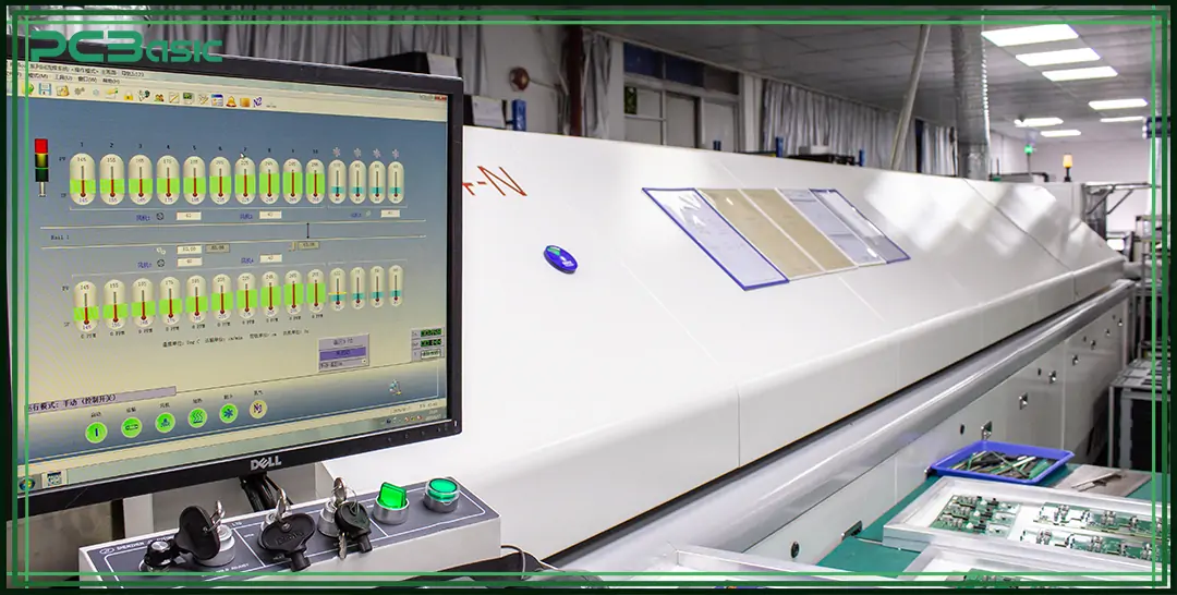
Reflow ovens assist in making electronic boards. The oven, using heat, warms up things up to 425°F. Then, it makes pieces hold firmly to the board. It has a conveyor belt that takes the board through various hot regions.
The first zone is used to gently preheat the board to prevent cracking. After that, the board travels to the soak zone, where the heat is spread out evenly across the entire board. At last, the solder in the reflow zone melts and joins all components with a good connection.
They employ nitrogen (N₂) to arrest rust. The oven has IR and hot air basting to promote even heat distribution. It also has thermocouples in various regions to monitor temperatures in different zones.
This is one of the most effective PCB mounting techniques in the electronics industry. Time spent in each zone ranges from 60 to 120 seconds. PCB mounting methods like this one form good connections.
Inside the oven, conveyors can accommodate boards up to 457 mm in width. Additional flux is caught by special systems, preventing the oven from getting dirty. That is why I have already mentioned that reflow ovens are perfect for producing many boards at once, and the percentage of mistakes is less than 0.1%. The whole process ensures that electronic devices bring out the best from a device.
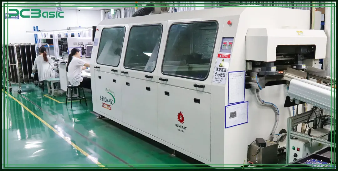
Wave soldering is one such cool PCB mounting technique. The machine works at a temperature not exceeding 260°C. It has components such as fluxers, preheaters, and coolers to assist with the process. PCB mounting methods ensure that the solder adheres well to the required points. PCBs are transferred through hot solder conveyors at the rate of 1.2 meters per minute. Flux at a concentration of 25 mg/cm² will be deposited on the board.
Nitrogen is incorporated to arrest rust at 300 ppm of nitrogen gas. This keeps the boards safe. These tricks are employed by PCB mounting methods to make things work right. The wave height is 12 mm, and the preheaters remain at a temperature of 150°C.
Infrared preheaters keep the heat just right. AOI is being used by sophisticated machines to look for errors. It helps to identify such issues quickly. The reason that soldering takes just 4 seconds to finish is that it's quick and solid.
That is why this method is wonderful for checking boards' functionality well. They ensure that the solder gets to all the connections and none of the parts get too hot. The result? Perfect PCBs every time.
An AOI system inspects circuit boards. PCBasic JS Technology Co., Ltd. systems take 25,000 frames per second, ensuring nothing is missed. It employs cameras with the capacity to take up to 25,000 frames per second to inspect parts. The system assists in identifying errors.
Then, it verifies if components such as SMDs (Surface-Mount Devices) are placed correctly. The lens is 12-megapixel, meaning the device is able to capture even the smallest of details. It will be possible to tell when there are misaligned pieces that should join a particular board, components that should be mounted but are missing, or some boards that were poorly soldered.
The chosen PCB Mounting Methods must have AOI for quality. AOI systems can inspect up to twenty tiers of a board. In the light, they use RGB LEDs. It takes 3 seconds for each board to be inspected. This process is very efficient indeed. AOI systems apply to boards ranging between 50mm and 500mm. They also measure the height of the solder paste and the lead width of the solder filters before it enters the furnace. This tool aids in ensuring that every board is good.
Aspect
Through-Hole Mounting
Surface-Mount Technology (SMT)
Mixed Technology
Direct-Bonded Chip (DBC)
Chip-On-Board (COB)
Flip-Chip Technology
Embedded Components
Component Size
Large (≥2.54mm pitch)
Small (≤0.5mm pitch)
Combines large & small
Medium
Very Small
Tiny
Varies (Small to Medium)
Board Area Usage
High
Low
Medium
Low
Very Low
Very Low
Low to Medium
Assembly Process
Manual/Semi-automatic
Automatic
Hybrid (manual + automatic)
Manual/Automatic
Manual
Automatic
Automatic
Reliability
High
Medium
High
Very High
High
Very High
High
Thermal Management
Good (due to through holes)
Fair
Variable (depends on design)
Excellent (ceramic substrate)
Fair
Good
Excellent (due to embedded layers)
Cost
High
Low
Medium
High
Medium
High
Medium to High
Application
Power electronics, High-stress areas
Consumer electronics, Mobile
Complex circuits
High-power devices
LED modules, Displays
High-performance computing
Advanced embedded systems
Table on PCB mounting methods
We discussed about the PCB mounting methods, such as through screws and clips. All methods make boards powerful when done. Go PCBasic to know more. This site helps you find the best strategies for mounting boards. And that's how good circuit boards are made.

Assembly Enquiry
Instant Quote
Phone contact

+86-755-27218592
In addition, we've prepared a Help Center. We recommend checking it before reaching out, as your question and its answer may already be clearly explained there.
Wechat Support

In addition, we've prepared a Help Center. We recommend checking it before reaching out, as your question and its answer may already be clearly explained there.
WhatsApp Support

In addition, we've prepared a Help Center. We recommend checking it before reaching out, as your question and its answer may already be clearly explained there.
