Ru

Help Center  
Sending a message
Open Hours:9:00-21:00 (GMT+8)
Service hotlines
+86-755-27218592

9:00 -18:00, Mon. - Fri. (GMT+8)

9:00 -12:00, Sat. (GMT+8)

(Except Chinese public holidays)

X

HomePage > Blog > Knowledge Base > Surface Mount vs. Through Hole: What are the Differences

Surface Mount vs. Through Hole: What are the Differences

3754

Introduction


Over the past few years, semiconductor packaging has undergone a notable transformation due to a rising need for enhanced functionality, reduced dimensions, and augmented versatility. 

When it comes to contemporary PCBA design, two primary techniques are employed for attaching components to a printed circuit board: through-hole technology and surface-mount technology.

However, you might wonder about the distinctions that set apart surface mounting and through-hole insertion. This article will shed light on the primary disparities between these two PCB assembly methods.

Surface Mount Technology (SMT)


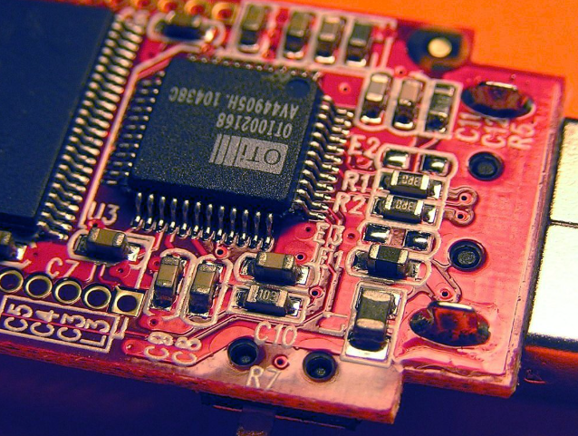
Surface-mount technology, commonly abbreviated as SMT, represents an innovative assembly and production methodology for directly attaching components onto a printed circuit board (PCB) positioned flush with its surface. This groundbreaking approach was conceived as a successor to the previously prevalent "through-hole technology."

The genesis of SMT can be traced back to the 1960s, with its widespread adoption only taking root in 1986 when surface-mounted components began to capture a substantial 10% market share. By the dawn of the 1990s, Surface-mount devices (SMDs) had firmly embedded themselves within most cutting-edge printed circuit assemblies.

IBM predominantly championed the pioneering work in the development of surface-mount technology. As early as 1960, IBM showcased its first practical demonstration of SMT, unveiling a compact computer model that later found application in the Launch Vehicle Digital Computer for the Instrument Unit, an instrumental component guiding both Saturn IB and Saturn V spacecraft.

Besides, surface-mount technology components were ingeniously designed with diminutive tabs or end caps, facilitating the application of solder to secure SMDs firmly onto the PCB's surface.

The time-consuming drilling process, tailored to fit each component snugly, was subsequently replaced by the SMT method, which prevented the need for these lead holes. The design of SMDs with reduced or no hole leads precipitated a seismic transformation in PCB assembly, yielding substantial advantages.

One of the most pronounced benefits of SMT was the ability to incorporate significantly smaller components while maintaining secure adhesion to the circuit board. Smaller components naturally engendered heightened component density, a development that found validation in the realms of "Moore's Law." Originally postulated to stipulate that the density of motherboard components would double annually from 1965 to 1975, it was subsequently amended to a biennial doubling rate.

Fast forward to the present day. SMT has ubiquitously infiltrated virtually every electronic device category, from children's toys and coffee makers to the ubiquitous smartphones and laptops that shape our digital lives. 
While the ever-evolving landscape of technology leaves room for novel methodologies, it is evident that surface-mount technology will remain an enduring and foundational facet of electronics manufacturing for the foreseeable future.

Terminology You Need to Know About SMT


In the realm of electronics manufacturing, there is a comprehensive set of terminologies associated with surface-mount technology (SMT):


● SMA (Surface-Mount Assembly): This denotes constructing or assembling a circuit or module utilizing the surface-mount technology (SMT).


● SMC (Surface-Mount Components): Refers to the various electronic elements specifically designed for employment in surface-mount technology (SMT) applications.


● SMD (Surface-Mount Devices): Encompasses a wide spectrum of electronic components, spanning both active and passive components, along with electromechanical elements, all intended for integration into SMT-based circuits.


● SME (Surface-Mount Equipment): Denotes the specialized machinery and equipment tailored for the execution of Surface-Mount Technology (SMT) assembly processes.


● SMP (Surface Mount Packages): Signifies the diverse housing forms or casings designed to accommodate surface-mount devices (SMDs) within electronic systems.


● SMT (Surface-Mount Technology): Encompasses the entire gamut of practices and techniques employed in the assembly and mounting of electronic components onto circuit boards, constituting a cornerstone of contemporary electronic technology manufacturing processes.

surface mount vs through hole


Types of Surface Mount Devices (SMD)


Surface Mount Devices (SMDs) encompass a broad spectrum of electronic components meticulously engineered for direct attachment to a printed circuit board (PCB) surface, eliminating the need for conventional through-holes or leads. 

These versatile components exhibit a wide array of shapes, dimensions, and functions, serving diverse roles within electronic circuitry. Among the various SMDs, the following are some of the most common examples:

● Surface Mount Resistors (SMD Resistors): These passive components regulate the flow of electrical current in a circuit, offering a multitude of resistance values and power ratings to suit various applications.


● Surface Mount Capacitors (SMD Capacitors): Capacitors responsible for storing and discharging electrical energy are available in various types, including ceramic, tantalum, and aluminum electrolytic variants.


● Surface Mount Inductors (SMD Inductors): These components store energy within magnetic fields and are predominantly deployed in filters and radio frequency (RF) circuits.


● Surface Mount Diodes (SMD Diodes): Diodes facilitating one-way current flow encompass standard diodes, Schottky diodes, and zener diodes within the realm of surface mount technology.


● Surface Mount Transistors (SMD Transistors): Transistors, pivotal semiconductor devices for amplification and switching, present an assortment of types such as NPN, PNP, N-channel, and P-channel MOSFETs in the SMD category.


● Surface Mount LEDs (SMD LEDs): Light-emitting diodes (LEDs), illuminating when electrical current traverses them, hold widespread usage in indicator lights and displays within the SMD category.


● Surface Mount Integrated Circuits (SMD ICs): These comprehensive electronic circuits, enclosed within a single package, may encompass microcontrollers, analog ICs, and digital ICs, among others.


● Surface Mount Connectors: Specifically designed for Surface Mount Technology (SMT) applications, these connectors establish electrical connections between PCBs or external devices.


● Surface Mount Switches: SMT switches fulfill various user interface and control functions. It comes in diverse types, such as push-button, tactile, and slide switches.


● Surface Mount Crystals and Oscillators: These components deliver precise timing and clock signals, crucial for the synchronization of electronic circuits.


● Surface Mount Transformers: SMT transformers play a vital role in power supplies and communication circuits by providing voltage transformation and isolation.


● Surface Mount Voltage Regulators: These components ensure a stable output voltage, playing a pivotal role in power management applications.

These represent merely a subset of the extensive range of surface mount devices accessible, with the selection of SMDs contingent upon the specific requisites of the electronic circuit or device under development. The compact dimensions and operational efficiency inherent to SMDs render them a fundamental choice within contemporary electronics manufacturing.

Advantages of Surface Mount Technology


1. Miniaturization Achievement


The dimensions and occupied volume of SMT electronic components significantly outshine their through-hole counterparts, often leading to reductions of 60% to 70%, with some components undergoing astonishing 90% size and volume reductions. Additionally, the weight of these components can be slashed by a substantial 60% to 90%.


2. Accelerated Signal Transmission


SMT assembly not only excels in compactness but also offers an impressive safety density, reaching assembly densities of 5.5 to 20 solder joints per square centimeter when applying PCBs on both sides. The resulting SMT-assembled PCBs facilitate high-speed signal transmission due to their minimal circuit length and minimal delay. Furthermore, the resilience of SMT-assembled PCBs against vibrations and impacts enhances their suitability for ultra-high-speed electronic operations.


3. Enhanced High-Frequency Performance


The absence of leads or the presence of short leads in SMT components naturally reduces the circuit's distributed parameters and mitigates radio frequency interference, culminating in favorable high-frequency characteristics.


4. Automation Advantages and Enhanced Production


SMT shines in automated production with standardized, serialized, and consistent welding conditions for chip components. This automation reduces component failures attributed to the soldering process, elevating overall reliability and enhancing production efficiency.


5. Economical Material Utilization


Efficiency improvements in production equipment and reduced packaging material consumption have driven down the packaging costs of most SMT components, rendering them more cost-effective than their through-hole technology (THT) counterparts of equivalent type and functionality. Consequently, SMT components are priced more competitively than THT components.


6. Streamlined Production Processes and Cost Reduction


When mounting components onto PCBs, the need to bend, shape, or trim component leads is obviated, streamlining the entire process and augmenting production efficiency. The processing cost for achieving the same functional circuit is typically lower than that of through-hole interpolation, generally resulting in total production cost reductions ranging from 30% to 50%.


Disadvantages of Surface Mount Technology


1. Costly Equipment Investment


The implementation of a Surface-Mount Technology (SMT) PCB assembly line necessitates a substantial financial commitment due to the high cost associated with SMT equipment, including reflow ovens, pick and place machines, solder paste screen printers, and hot air SMD rework stations.


2. Challenging Inspection Process


The inspection of SMT assemblies poses notable challenges, primarily because most surface-mount components are diminutive and boast numerous solder joints. Components with Ball Grid Array (BGA) packaging introduce further complexity, as their solder balls and joints are concealed beneath the component, making inspection a daunting task. Moreover, the equipment employed for SMT inspection comes with a hefty price tag.


3. Vulnerability to Damage


SMD components are susceptible to damage, especially if mishandled or dropped. Their sensitivity to Electrostatic Discharge (ESD) necessitates specialized ESD products for safe handling and packaging. Typically, SMD components are managed within a controlled cleanroom environment to mitigate the risk of damage.


4. Expensive Small-Scale Production


The production of SMT PCB prototypes or small-scale batches can be financially demanding. Moreover, the process involves technical intricacies that require a high level of expertise and training.


5. Limited Power Availability


Surface-mount technology does not encompass all active and passive electronic components, resulting in constraints in terms of available power. Generally, SMD components tend to have lower power ratings than their through-hole counterparts.


Through Hole Technology


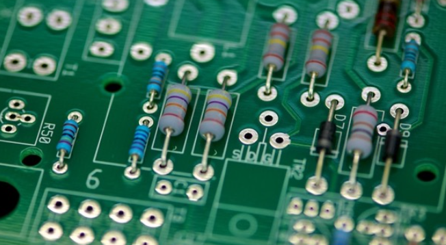
Through-hole mounting involves inserting component leads into meticulously drilled holes within a bare PCB. Before the advent of SMT in the 1980s, through-hole technology stood as the prevailing industry-standard configuration method. 

Although the efficiency and cost-effectiveness of the surface mount have propelled it to the forefront, predicting the obsolescence of through hole might be premature.

Notably, the through-hole technique, while facing a decline in popularity, has proven to be remarkably versatile in the era of SMT, offering various advantages and specialized applications. One standout attribute of through-hole technology is its inherent durability, and this durability is now often reinforced by the presence of annular rings, ensuring robust connections that withstand the test of time.

through hole technology


Axial vs. Radial Leads


Within the realm of through-hole components, there are two primary classifications: radial and axial components, each with unique characteristics. Axial leads traverse a component in a straight line, emerging from both ends ("axially") and fitting through separate holes on the board. 

Both radial and axial components are considered "twin" lead components, each offering distinct advantages. Axial lead components are favored for their snug integration with the board, ensuring a secure connection. On the other hand, radial leads are well-suited for compact, high-density boards where space is scarce, thanks to their minimal surface footprint.

Meanwhile, radial lead components are commonly represented by disk capacitors. These variations in lead configuration cater to a spectrum of electronic design requirements and preferences.

Advantages of Through Hole Technology


1. Elevated Reliability


Through-hole technology (THT) PCB assembly boasts superior reliability compared to surface mount technology (SMT) assembly. Its heightened reliability stems from the physical anchoring of components to the board through holes and soldering, mitigating the risk of components becoming dislodged or detached during operation. Furthermore, THT components exhibit robustness in handling higher current and voltage levels, rendering them ideal for applications demanding substantial power.


2. Cost Efficiency


THT PCB assemblies typically come with a lower price tag than their SMT counterparts. This cost advantage can be attributed to the reduced expenses associated with THT components and the simplified assembly process. The larger size of THT components not only makes them more manageable during assembly but also diminishes the likelihood of damage, ultimately leading to cost savings. Additionally, their ease of sourcing and affordability in the market contribute to cost-effectiveness.


3. Seamless Repair and Replacement


THT PCB assembly facilitates straightforward repairs and component replacements. The through-hole design simplifies the identification and exchange of faulty components, as well as the repair of damaged wiring and through-holes. Furthermore, THT components can be easily extracted and replaced using a soldering iron, eliminating the need for specialized equipment.


Disadvantages of Through Hole Technology


1. Restricted Component Density


Through-hole technology PCBA suffers from a limitation in component density. It arises from the fact that components are positioned on one side of the board, with their leads threaded through holes to the opposite side. Consequently, components must be spaced at wider intervals to prevent lead-to-lead contact. Consequently, THT PCBs tend to be bulkier and consume more physical space than surface mount technology (SMT).


2. Manual Assembly Process


THT PCB assembly is predominantly a manual endeavor demanding high skill and precision. Components are meticulously positioned on one side of the board, and their leads are then threaded through holes to the opposite side, followed by bending and soldering. This labor-intensive process is inherently time-consuming and susceptible to human errors. Furthermore, the manual nature of assembly complicates the prospects of automating THT PCB production, hindering efficiency gains.


3. Elevated Risk of Component Damage


There is a high risk of damaging components throughout the manual assembly process. The insertion of leads can result in bending or breakage, rendering components non-operational. Additionally, the soldering process, if not meticulously temperature-controlled, can expose components to excessive heat, leading to potential damage. These factors contribute to increased defect rates and reduced production yields.


Key Differences Between Through-Hole and Surface Mount Technologies


Here, we explore the critical distinctions between through hole vs. surface mount.

1. Interconnection Strength


Through-Hole Components: Through-hole components are known for their robust interconnections. Their leads run through the circuit board, providing stronger and more durable connections between layers.

Surface Mount Components: In contrast, SMT components are secured solely by solder on the board's surface, which can be less resilient in the face of environmental stress.

2. Environmental Resilience


Through-Hole Components: Through-hole technology excels in environments where products may experience extreme conditions such as rapid accelerations, high-velocity collisions, or extreme temperatures. Its penetrating connections allow components to withstand these stresses effectively.

Surface Mount Components: SMT components are generally less adept at handling extreme environmental conditions due to their surface-only solder connections.

3. Industry Applications


Through-Hole Components: Through-hole technology finds its niche in high-reliability industries like military and aerospace. These sectors require components that can endure harsh conditions, making through-hole components the preferred choice.

Surface Mount Components: SMT components are more commonly used in consumer electronics and applications where environmental stress is not a primary concern.

4. Versatility in Testing and Prototyping


Through-Hole Components: Through-hole components are well-suited for testing and prototyping applications. Their penetrable connections make manual adjustments and component replacements relatively straightforward.

Surface Mount Components: SMT components can be more challenging to work with in testing and prototyping scenarios, as they are typically soldered to the surface without easy access for manual adjustments.

In summary, the choice between through-hole and surface mount technology depends on the specific requirements of a project. Through-hole technology offers superior reliability and resilience in demanding environments, making it a top choice for high-stress applications. In contrast, surface mount technology excels in more standard consumer electronics and applications where environmental stress is less of a concern.

So this is the prime difference between thru hole vs. surface mount.

Other Types of PCB Assembly 


Besides surface mount and through hole techniques, there are a few other PCBA methods as well. Below are a few.

Rigid-Flex PCBA


Rigid-flex PCBs represent a harmonious convergence of rigid and flexible circuit board technologies. These specialized printed circuit boards are engineered to integrate the attributes of both rigid and flexible substrates. Components will be mounted onto both rigid and flexible parts of the board.

The core of rigid-flex PCBs typically comprises several tiers of pliable circuit substrates, intricately connected either externally or internally to single or multiple rigid panels. This design flexibility caters to the unique requirements of diverse applications.

Mixed Assembly


In the ever-evolving landscape of PCB production, surface mount technology (SMT) has undeniably risen to prominence. However, the complexity of modern electronic devices sometimes necessitates a blend of assembly methods. 

In such scenarios, a combination of surface mount and through-hole technology becomes imperative on the same PCB. This amalgamation of assembly techniques, executed without using solder paste during production, is aptly termed "mixed assembly" or "hybrid assembly."

BGA Assembly


Ball grid arrays (BGAs), also called chip carriers, represent a cutting-edge facet of surface-mount technology. These innovative packages are specifically engineered for encapsulating integrated circuits with precision. When it comes to permanent installations of crucial components like microprocessors, BGA packaging reigns supreme.

Comparatively, traditional dual in-line or flat packages pale in terms of connector pin capacity. BGAs harness the full expanse of their bottom surface for connectivity, offering a substantial advantage over their predecessors by maximizing the utilization of available space.

Conclusion


In conclusion, our exploration of modern PCB assembly technologies has shed light on the pivotal role of both surface mount technology and through-hole technology in the electronic industry. The coexistence of these two approaches underscores the necessity for adaptability and customization in PCB production.

Surface mount technology, with its dominance in contemporary electronics, offers space-saving advantages and streamlined assembly processes, making it ideal for a wide range of consumer electronics and compact devices. 

On the other hand, through-hole components and technology remain indispensable for applications demanding robust interconnections and resilience in harsh environmental conditions, such as those found in the military and aerospace sectors.

Additionally, the article delved into the intriguing realm of rigid-flex PCBs and mixed assembly. The latter seamlessly integrates both SMT and THT approaches to cater to specialized requirements. 

Furthermore, the introduction of the Ball Grid Array (BGA) assembly exemplifies the industry's relentless pursuit of space optimization and enhanced connectivity, especially relevant for high-performance microprocessors and integrated circuits.

In essence, SMT and THT continue to be the foundation upon which modern electronics are built, with each technology offering unique advantages that cater to a broad spectrum of applications and challenges. The dynamic interplay between these methodologies is a testament to the adaptability and innovation driving the electronic industry forward. Hopefully, you have now understood the difference between surface mount and through hole.


Looking for a PCB or PCBA quote? Contact us now.


Citations:

About Author

Leading Printed Circuit Board Assembly(PCBA) Manufacturer

Assemble 20 PCBs for $0

E-mail

Quote

0.630220s