Global high-mix volume high-speed PCBA manufacturer
9:00 -18:00, Mon. - Fri. (GMT+8)
9:00 -12:00, Sat. (GMT+8)
(Except Chinese public holidays)
Global high-mix volume high-speed PCBA manufacturer
9:00 -18:00, Mon. - Fri. (GMT+8)
9:00 -12:00, Sat. (GMT+8)
(Except Chinese public holidays)
HomePage > Blog > Knowledge Base > Counterbore Holes in PCBs
Mounting a circuit board isn’t as simple as screwing it into place. Especially not today. Modern devices are compact. They are stacked, layered, and sealed tight. So, any component that sticks out—like a screw head—can throw off the entire design.
That’s where PCB counterbores come in. They don’t look like much. Just a wider, shallow section at the top of a hole. However, they solve real mechanical and electrical problems. And in many devices, they are absolutely essential.
If you are designing a board for production, and it needs to be mounted securely, you’ll want to understand the counterbore hole inside and out. So, what is a counterbore? And why does it matter so much?
Let’s break it down.
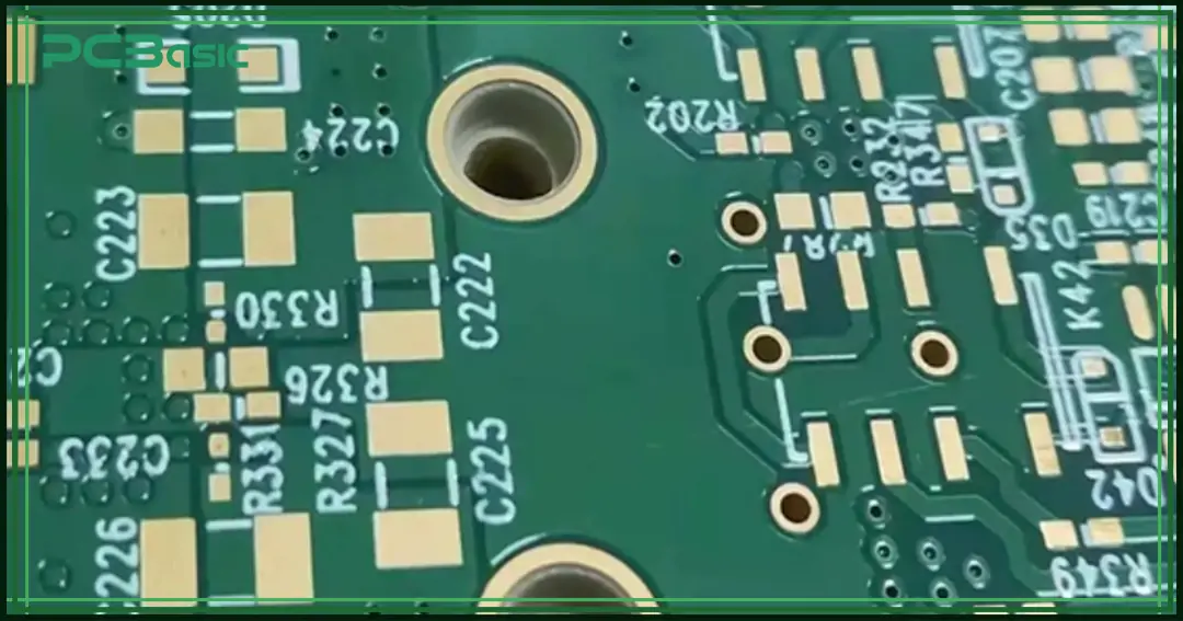
Let’s start with the basics. A counterbore is a flat-bottomed cylindrical recess. It’s drilled at the top of a hole to allow fastener heads—like socket screws or bolts—to sit flush with the surface. That way, nothing protrudes.
In PCB terms, a counterbore is a modification to a standard mounting hole. It's made wider at the top, with a precise depth, so the screw head fits perfectly inside.
Now, here’s why that matters. A printed circuit board (PCB) isn’t very thick—usually 1.6 mm for standard boards. That doesn’t leave much room for error. If the screw sticks out, even a little, it can cause problems. It might press against a casing, another part, or even a second PCB stacked above.
A counterbore solves that. It creates a small pocket where the screw head can sit flush. That way, nothing sticks out, and the board stays strong. And no, you can’t just drill a bigger hole and hope it works. That weakens the material and doesn’t hold the screw properly.
On engineering drawings, everything must be crystal clear. No room for guessing. That’s where symbols come in.
The counterbore symbol looks like this:

It’s followed by two dimensions:
• The diameter of the
counterbore.
• The depth of the counterbore.
Example:
This means a counterbore with a 6.5 mm diameter and a depth of 3.0 mm. You’ll usually find this symbol in mechanical drawings, especially in manufacturing documents that include PCBs or enclosures.
Why does the symbol matter? Because a misunderstanding at this stage can lead to the wrong hole size, faulty installation, or damage to the board. That can be costly. Or even catastrophic if the board is part of a critical system.
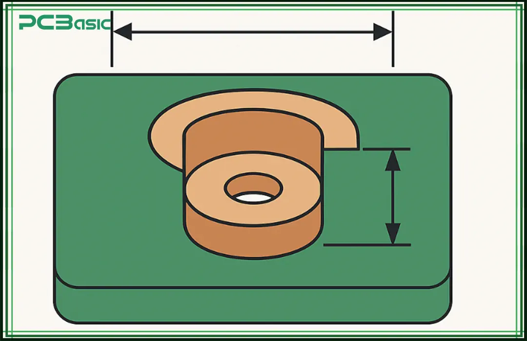
Here, a question arises: why not just use regular holes? Why bother with counterbores at all? Here’s the deal. In PCB assemblies, space is tight. And even tiny design details can create big problems down the line.
Let’s walk through the main reasons counterbores matter.
This is the big one. Counterbores allow screws to sit flush—or even slightly recessed—into the PCB. That means no protruding fasteners. No interference with enclosures. No scratches on internal casing surfaces.
In small devices like smartwatches, wearables, or medical devices, there’s literally no extra room. A 1 mm bump can ruin the design.
Many modern assemblies use multiple PCBs layered together. Standoffs, spacers, or posts separate them. And those boards are often held together with screws.
But here’s the catch—if the screw head on the lower board sticks out, the top board can’t sit flat. Counterbores solve that by hiding the screw head inside the board. Now, the upper PCB can rest directly on top, keeping everything neat and level.
This one’s a bit more advanced, but it’s important. Some designs use metal standoffs and screws not just for mounting, but for electrical grounding. In these cases, you need consistent, tight metal-to-metal contact.
A counterbore helps. It ensures the screw head is pressed firmly against a copper ground pad or mounting ring, giving you reliable grounding and better electromagnetic shielding.
Bad grounding leads to EMI issues. That means interference, failed tests, and expensive rework.
In automotive or industrial PCBs, vibration is a serious concern. Fasteners need to hold tight. A screw head sitting flush in a counterbore spreads the load evenly. It reduces movement, which reduces the chance of mechanical failure.
Sometimes, it's about looks, too. In premium consumer electronics—think smartphones or tablets—internals are often designed with aesthetics in mind. Even the placement and depth of screws are carefully managed.
Counterbores help create a seamless internal structure. That matters more than you’d think, especially in high-end products.
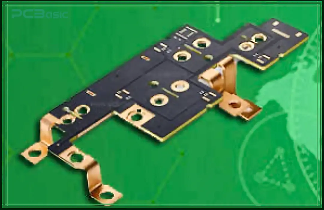
Here are some real-world examples of where you’ll find counterbores on PCBs:
• Consumer Electronics: Devices
like smartphones or tablets often use stacked board layouts. Screws with
counterbores help keep the layers tight and secure.
• Industrial Equipment: Machines
shake, a lot. That’s why vibration-resistant mounts are used. Counterbores help
by keeping screws tight and secure, even under constant motion.
• Automotive Electronics: Cars go
through heat, cold, bumps, and jolts. There’s no room for loose hardware.
Counterbores make sure PCBs stay firmly in place. This way, they reduce strain
over time.
• Medical Devices: Precision is
critical. Counterbores allow accurate mounting in compact enclosures.
• Aerospace Systems: Every gram and millimeter matters. Flush mounting is a necessity.
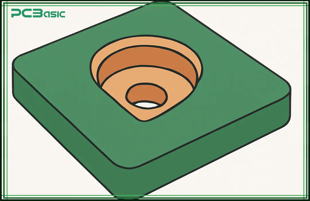
Designing a counterbore isn’t hard. But it needs to be precise. A wrong move—too deep, too wide, or off-center—can weaken the board or ruin the assembly.
Here’s what to keep in mind:
Not all PCBs are the same. Most are 1.6 mm thick, especially in standard builds. But power boards tend to be thicker. Flex-rigid designs? Often thinner.
You need to make sure the counterbore depth doesn’t go too far. If the recess cuts too close to a copper layer, it can expose traces or reduce mechanical strength.
Rule of thumb:
Leave at least 0.3 mm between the bottom of the counterbore and the nearest copper layer or hole.
Not all mounting holes are plated. If your counterbore leads to a plated through-hole, that’s fine—but remember, plating adds thickness.
A typical via wall is 25–50 µm. It doesn’t affect the counterbore too much unless the diameter is very small. Still, your manufacturer needs to know if it’s a plated or non-plated hole, especially when applying surface finish or cleaning the cavity.
FR-4 is strong, but it’s still fiberglass and epoxy. If the screw head applies too much pressure, it can crush the board.
Counterbores reduce the material above the screw head. That can make the board more fragile around mounting holes. To fix that, many designs include a metal washer or a copper pad under the screw to distribute the force.
In some high-stress applications, designers use mechanical inserts—metal sleeves that reinforce the counterbored hole.
Drilling counterbores requires specific tool sizes. You can’t assume your manufacturer has every drill bit diameter available.
Before finalizing the design, check your PCB fab shop’s capabilities. Most work with fixed toolsets—often in 0.05 mm increments. If your counterbore is, say, 3.73 mm wide, they’ll round it up or down. That might cause misfits during assembly.
This one’s often missed. If the screw is part of a grounding path, you need metal contact. That means no solder mask inside the counterbore. Otherwise, the mask acts like an insulator.
Specify mask clearance around the counterbore in your fab notes. Better yet, use a copper ring or annular pad to ensure proper contact and conductivity.
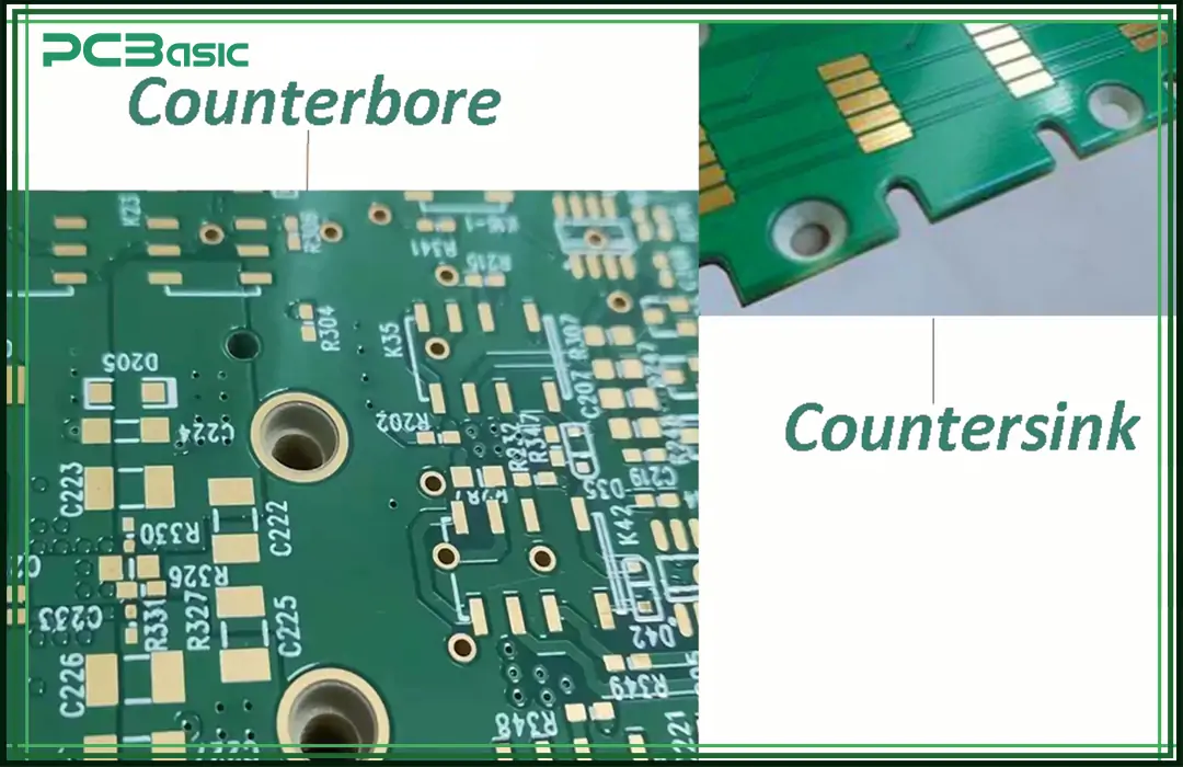
People often confuse counterbores with countersinks. They sound similar, but they are not the same thing. Let’s clear that up.
|
Feature |
Counterbore |
Countersink |
|
Shape |
Cylindrical recess with flat bottom |
Conical recess with angled sides |
|
Used for |
Socket head screws, bolts |
Flat head screws |
|
Symbol |
⌴ |
⌵ |
|
Mounting Result |
Screw sits flat or below surface |
Screw head tapers into the board |
|
Preferred In |
PCBs, mechanical assemblies |
Thin sheet metal, sometimes in PCBs |
|
Angle |
90° walls |
82°, 90°, or 100° cone |
In PCBs, counterbores are more common. Especially when designers want flat screw heads. Countersinks are rare, but they do appear in special cases—usually when using flat-head screws for aesthetic reasons or when designing enclosures with tapered entry points.
There’s also a mechanical difference. Countersinks concentrate stress at the screw head’s edge, which can crack a PCB if the material is thin. Counterbores spread the load evenly, making them more suitable for fragile or layered assemblies.
So, when in doubt—choose a counterbore for PCB applications. It’s safer, easier to machine, and gives more flexibility in hardware selection.
Counterbores don’t get much attention. But they solve real problems. They make your boards easier to mount. Also, they help components sit properly and prevent interference with enclosures. Sometimes, they improve grounding and shielding, too.
If you’re designing a board that needs to be stacked, enclosed, or mounted with precision—don’t overlook the counterbore.
Just remember to use the right symbol in your mechanical drawings. Moreover, specify the exact depth and diameter. Watch out for board thickness and material strength. Plus, communicate clearly with your PCB team. It’s a small detail. However, in PCB design, small details often make the biggest difference.
Need help with fabrication drawings or PCB stack-ups? Always check your manufacturer’s DFM (Design for Manufacturability) guidelines.

Assembly Enquiry
Instant Quote
Phone contact

+86-755-27218592
In addition, we've prepared a Help Center. We recommend checking it before reaching out, as your question and its answer may already be clearly explained there.
Wechat Support

In addition, we've prepared a Help Center. We recommend checking it before reaching out, as your question and its answer may already be clearly explained there.
WhatsApp Support

In addition, we've prepared a Help Center. We recommend checking it before reaching out, as your question and its answer may already be clearly explained there.
