Global high-mix volume high-speed PCBA manufacturer
9:00 -18:00, Mon. - Fri. (GMT+8)
9:00 -12:00, Sat. (GMT+8)
(Except Chinese public holidays)
Global high-mix volume high-speed PCBA manufacturer
9:00 -18:00, Mon. - Fri. (GMT+8)
9:00 -12:00, Sat. (GMT+8)
(Except Chinese public holidays)
HomePage > Blog > Knowledge Base > 4-Layer PCBs: Stack-Up, Thickness, and Design Tips
As we all know, there are different layers of circuit boards on the market, from single layer, double layers, to multi layers. Among them, 4-layer PCBs become the ideal balance point between complexity, cost and performance.
Compared to 2-layer PCBs, four-layer PCBs significantly improve signal integrity through additional power and ground planes, while being more economical than 6-layer PCBs and more layer PCBs.
This article will delve into the layered structure, core benefits and key design tips of 4-layer PCBs to help you better understand 4-layer PCBs.
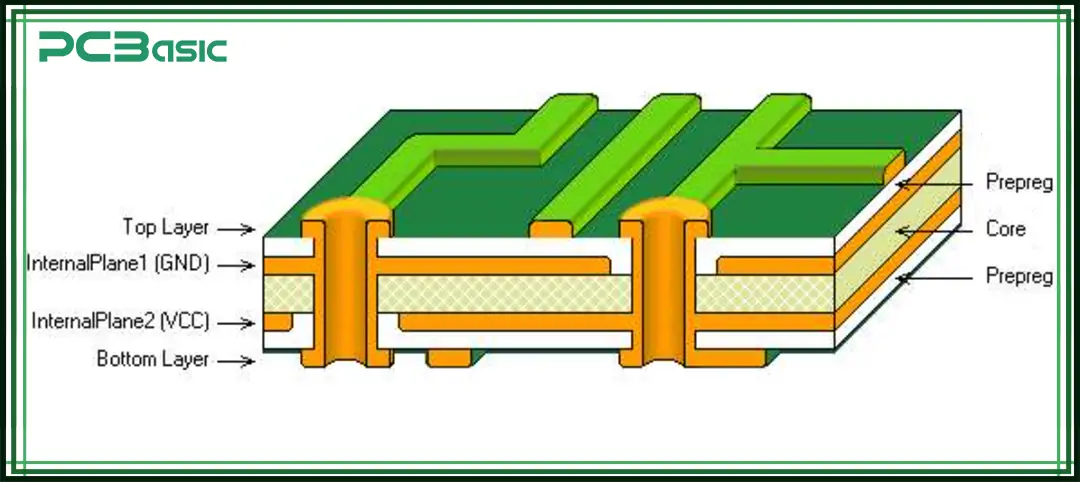
A 4-layer PCB is a circuit board with 4 layers of copper conductive layers separated by insulating materials. In general, the outer two layers of the 4-layer PCB are used for signal routing, and the inner two layers are used for power and ground. Such a structure can reduce electromagnetic interference (EMI), make the signal more stable, very suitable for the function of complex circuit boards.
Compared with standard double-sided boards, a 4-layer PCB can allow for more routing space, put more components, and better heat dissipation effect, which makes it more suitable for high-performance electronic products.
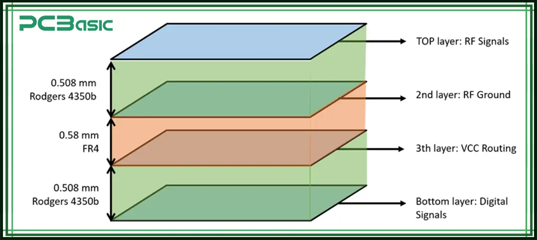
There are several 4-layer PCB stack-up options, depending on whether you prioritize EMI shielding, signal integrity, or power distribution. The following are the two most typical 4-layer PCB stack-up options:
Option 1: Symmetrical Stack-Up (Recommended)
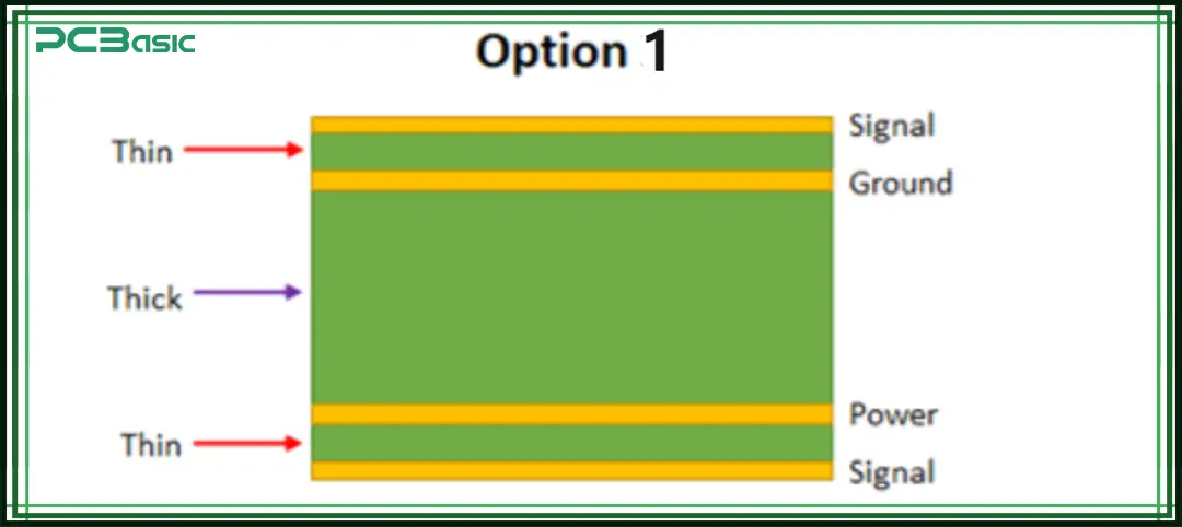
|
Layer |
Type |
Thickness (Typical) |
Function |
|
L1 |
Signal Layer |
0.2 mm |
High-speed signals, key component layout |
|
L2 |
Ground Plane (GND) |
0.5 mm |
Provides a low-impedance return path |
|
L3 |
Power Plane (VCC) |
0.5 mm |
Reduces power noise |
|
L4 |
Signal Layer |
0.2 mm |
Low-speed signals, secondary routing |
Advantages:
• Power and ground planes are adjacent, forming natural decoupling capacitance to suppress high-frequency noise
• Signal layers are closely coupled to reference planes, minimizing crosstalk
Option 2: Asymmetrical Stack-Up (Low Cost)
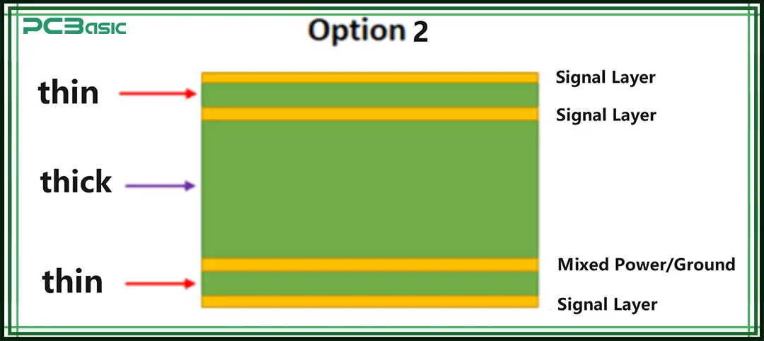
|
Layer |
Type |
Thickness |
Risk |
|
L1 |
Signal Layer |
0.1 mm |
Susceptible to manufacturing variations |
|
L2 |
Signal Layer |
0.6 mm |
Potential impedance discontinuity |
|
L3 |
Mixed Power/Ground |
0.6 mm |
Poor power integrity |
|
L4 |
Signal Layer |
0.1 mm |
Prone to warping during assembly |
Application Scenario:
Suitable for cost-sensitive applications without high-speed signals.
The standard thickness of a 4-layer PCB is generally 1.6mm (0.063 inches) (including the 4 layers and 2 layers of prepreg and 1 layer of core), but it can also be made between 0.8mm and 3.2mm according to needs. This thickness of a 4-layer PCB not only ensures that the PCB is strong enough but also allows the internal structure to be arranged more flexibly.
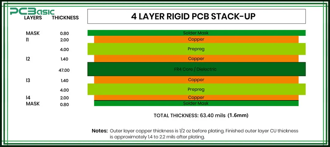
Choosing the right 4-layer PCB thickness is very important, as it can affect the impedance of the signal lines, the distance between the layers, and the heat dissipation effect of the entire PCB. It is recommended to communicate with the PCB manufacturer before design to ensure that the board produced meets the design requirements and can be smoothly produced.
When designing a 4-layer PCB, a reasonable stack-up structure and routing method are crucial to the performance, stability and manufacturability of the circuit. The following are common 4-layer PCB design tips to help you avoid common problems and improve the quality of your design.
• Follow the "3:1 rule”: The thickness of the core layer should be more than 3 times the thickness of the outer dielectric thickness, which helps to improve the stability of the PCB.
• Avoid placing high-speed signals on both the top and bottom layers to reduce the risk of crosstalk.
• The use of through holes is preferred to avoid the high cost of blind holes and buried holes.
• Add anti-pads to the power or ground planes to prevent from shorting to unintended areas.
• Maintain adequate spacing between different voltage zones to avoid electrical interference.
• Place decoupling capacitors at each power pin to improve power stability.
To ensure that high-speed signals (such as USB and HDMI) transmit accurately on a PCB without distortion, impedance matching must be properly controlled. Different signal types require different target impedances:
|
Signal Type |
Target Impedance |
Recommended Trace Width (1oz Copper) |
Dielectric Thickness |
|
USB Differential Pair |
90Ω |
0.15 mm |
0.2 mm |
|
Single-Ended Signal (e.g., SPI) |
50Ω |
0.3 mm |
0.2 mm |
At PCBasic, we focus on delivering high-performance, 4-layer PCB manufacturing and assembly services. Our expert team—with over 10 years of experience in PCB design and project management—ensures each board is optimized for signal integrity, power distribution, and thermal performance.
We operate multiple self-owned factories, including a small-batch plant in Shenzhen and a mass production facility in Huizhou, enabling us to handle orders of any volume efficiently. Our factories are equipped with self-operated stencil and fixture production, and high-speed SMT lines for reliable multilayer PCB fabrication.
From stencil delivery within 1 hour to intelligent electronic components warehousing, we provide a seamless assembly workflow. Our one-click BOM import system and instant quoting platform simplify the procurement and production process, ensuring fast and accurate project execution.
Quality is at the core of everything we do. PCBasic uses automated optical inspection (AOI), X-ray inspection, flying probe testers, and functional testing systems to ensure every 4-layer PCB meets stringent quality standards. Each board is thoroughly verified for accuracy, reliability, and performance before shipment.
As a national high-tech enterprise, PCBasic holds certifications, including ISO13485, IATF 16949, ISO9001, ISO14001, and UL, and is a proud IPC member. With over 20 patents in quality inspection and production management, we guarantee top-tier reliability and compliance with international standards.
Q1: How much more expensive is a 4-layer PCB compared to a double-sided PCB?
A: Typically, it costs 30–50% more, but the cost can be reduced by optimizing the material (e.g., using FR-4 Tg130) and minimizing the number of vias.
Q2: Is full copper pour necessary on all layers?
A: It is recommended to use full copper pour on L2 and L3 (power and ground planes). L1 and L4 (signal layers) can use partial copper pour, avoiding “copper islands.”
Q3: How can I verify the stack-up parameters?
A: You can use Polar SI9000 or Altium Layer Stack Manager for impedance simulation and validation.

Assembly Enquiry
Instant Quote
Phone contact

+86-755-27218592
In addition, we've prepared a Help Center. We recommend checking it before reaching out, as your question and its answer may already be clearly explained there.
Wechat Support

In addition, we've prepared a Help Center. We recommend checking it before reaching out, as your question and its answer may already be clearly explained there.
WhatsApp Support

In addition, we've prepared a Help Center. We recommend checking it before reaching out, as your question and its answer may already be clearly explained there.
