Global high-mix volume high-speed PCBA manufacturer
9:00 -18:00, Mon. - Fri. (GMT+8)
9:00 -12:00, Sat. (GMT+8)
(Except Chinese public holidays)
Global high-mix volume high-speed PCBA manufacturer
9:00 -18:00, Mon. - Fri. (GMT+8)
9:00 -12:00, Sat. (GMT+8)
(Except Chinese public holidays)
HomePage > Blog > Knowledge Base > Hall Effect Sensor Pinout | A Comprehensive Guide
Hall Effect Sensors are becoming critical with increasing levels of digitization. They are used widely in a number of applications ranging from car industries to home electronics products. The Hall Effect sensor market size around the world stood at nearly $2.3 billion in 2023, and the market is expected to grow at a CAGR greater than 13.5% in the upcoming 10 years.
The surge in the cablevey system production is expected to enhance significantly due to the growing demands in electric vehicle and automation technologies. In these sensors, the hall effect is employed to provide a method to translate magnetic fields into electric signals. These are essential in management of movement and operation of electronic devices.
This is an essential skill any engineer or hobbyist ought to know since having a clue of Hall effect sensors pinout assists in the integration process. Now let us look at the subject, focusing on Hall effect sensor pinouts, including their configurations and roles.
A Hall effect sensor is an electronic device that averts or measures magnetic fields and translates them into an electric variation. These sensors derive their names from the physicist Edwin Hall who discovered them in 1879 and they are applied in automotive systems, industrial machinery, and consumer electronics among other uses. What we can know about our surroundings we can also measure and infer without having to touch or be very close to the object being measured. Of this non-contact feature makes the Hall effect sensors rather robust and reliable for many applications.
These sensors develop a small voltage when an electrical current passes through a conductor exposed to magnetic field. The amount of voltage developed is called Hall voltage and it gives a measure of strength and direction of the magnetic field. This type of sensor uniformly named hall effect sensors are very central to the modern technology as it is very useful when it comes to measurements.
 About PCBasic
Time is money in your projects – and PCBasic gets it. PCBasic is a PCB assembly company that delivers fast, flawless results every time. Our comprehensive PCB assembly services include expert engineering support at every step, ensuring top quality in every board. As a leading PCB assembly manufacturer, we provide a one-stop solution that streamlines your supply chain. Partner with our advanced PCB prototype factory for quick turnarounds and superior results you can trust.
The limit on flow among the conducting material is called Hall effect and it is experienced where a magnetic field is passed perpendicular to the electric current in the substance. Electrons from the conductor experience a force due to the magnetic field when passing through it and as a result bend from a straight path. Such deviation leads to an accumulation of charge on one side of the conductor and this outcome gives rise to voltage.
This voltage is produced across the sensor and it depends on the strength of magnetic field being experienced. In fact, changes in the value of the magnetic field also imply changes in the Hall voltage. This principle makes Hall effect sensors to be useful in detecting magnetic fields, whether they are present or strong. These can be applied to many different objectives, such as determining the position of doors or even measuring the speed of rotating bodies.

Hall effect sensors can be categorized into several types based on their output and functionality:
❖ Analog Hall Effect Sensors: These sensors gives a continuous output voltage that is directly related to the strength of the magnetic field. They are typically used for the applications when high accuracy of measures is needed, for example, in the automotive industry for throttle position sensors or current measurements.
❖ Digital Hall Effect Sensors: It should be noted that digital Hall effect sensors can only provide two distinct outputs – high and low. They often contain more circuits such as Schmitt triggers that help in reducing fluctuations in the output signal. These sensors are familiar in such uses as in proximity switches and speed measurement.
❖ Linear vs. Latching Hall Effect Sensors:
❖ Linear Hall Effect Sensors: These sensors generate an output proportional with the changes of the applied magnetic field. It is mainly suitable for those processes that must be monitored continuously.
❖ Latching Hall Effect Sensors: These sensors turn on when they are in contact with a positive magnetic field and stays on even after the magnet is withdrawn. They switch off only if the body gets exposed to negative magnetic field. Latching sensors find uses in applications such as position sensing whereby constant monitoring and updating of state is important.
Hall Effect sensors usually come in three leads/connections, most of them having an optional fourth lead. All the pins have certain roles in powering the sensor and sending signals. Here's a breakdown of their functions:
● Pin 1 Vcc (Positive Terminal / Supply Voltage): This pin gives power to the sensor for its operation. They perform the role of supplying power to the working circuit of the sensor. Depending on the make and model of the sensor, it jiggers the positive terminal of the power supply, and this might be 3.3V, 5V, or 12V at most.
● Pin 2 Ground (GND): The Ground pin on the USB connector closes the circuit and is connected to the negative terminal on the power supply. It also means that the system remains well grounded hence the operation is stable and electrical noises cannot interfere with the operation of the sensor.
● Pin 3 Output (Signal Pin): The Output pin displays information that the sensor has detected, a magnetic field being one of them, its strength included. For the analog sensor, this is where the varied voltage for the corresponding magnetic field is obtained. The control signals applied to the chip are digital sensors, and they either have high or low status.
● Pin 4 (Optional - For 4-pin Sensors): Some sensors have pin connections consisting of only 4 pins. However, this connector does not necessarily mean that all the pins are used for the placement of wires. Newer Hall Effect sensors may have a fourth pin added to the circuit to switch the sensor on and off or indicate to the user if it is working. In general, this pin's function can be established by almost any sensor, but consult the datasheet for the particular sensor you are using.

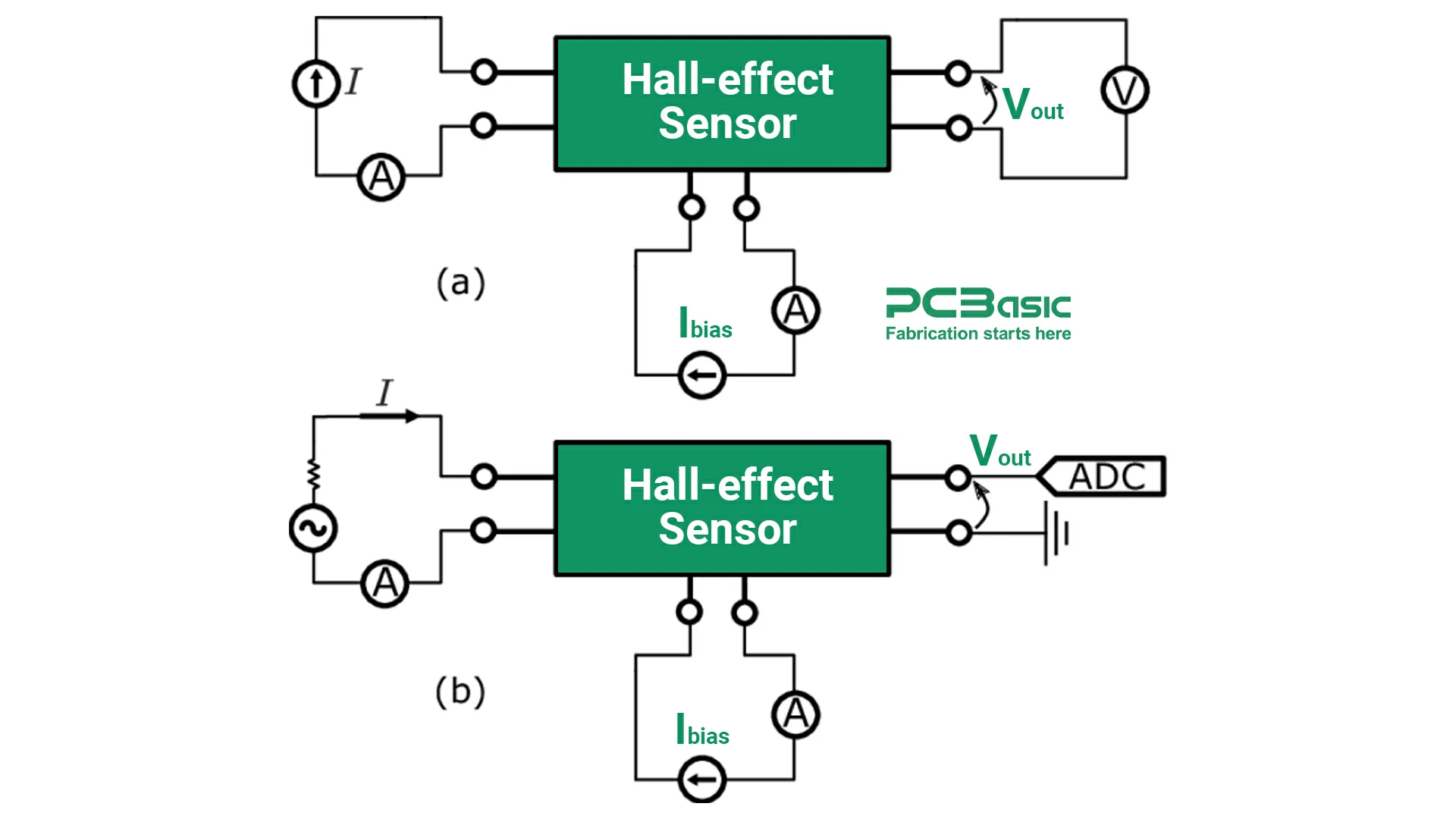
Visual forms assist in the comprehension of Hall effect sensor connections. The usage of a diagram might be very useful for emphasizing the most common pinouts and the tasks they perform.
● Visual representation of common Hall Effect sensor pinouts: Each pin is generally labeled to depict its role, in order to help users to understand certain relations. Here also these illustrations let you learn how to connect the sensor correctly in the least time.
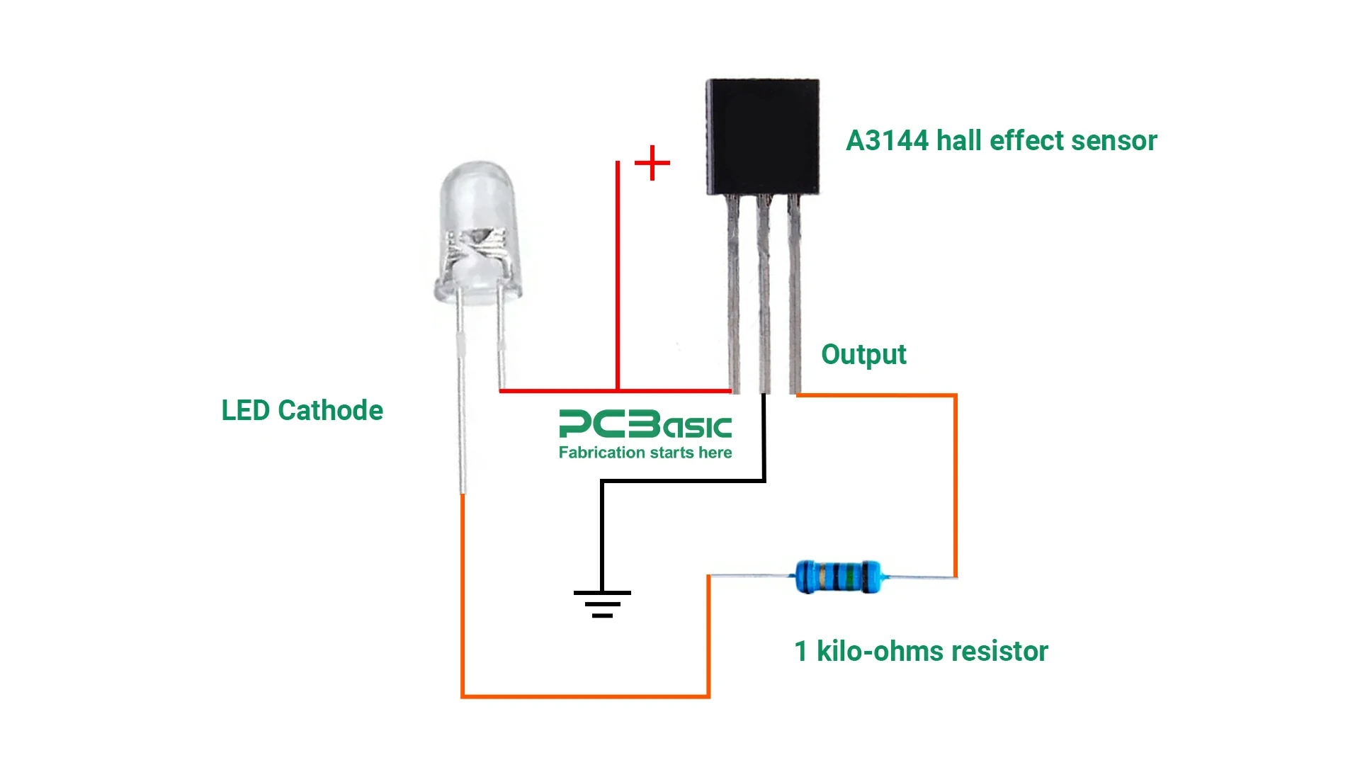
● Example circuit diagram showing the wiring of a Hall Effect sensor: A basic circuit diagram should be able to illustrate how one can connect a Hall Effect sensor to a microcontroller, for instance, an Arduino. To the diagram normally depicts input pins, such as Vcc and GND, output pins, and other features, such as resistors or capacitors to enable high functionality. This form of representation makes it easy to tell where to connect since you see the whole setup process clearly.
What is a Hall Probe, and How Does it Relate to the sensor?
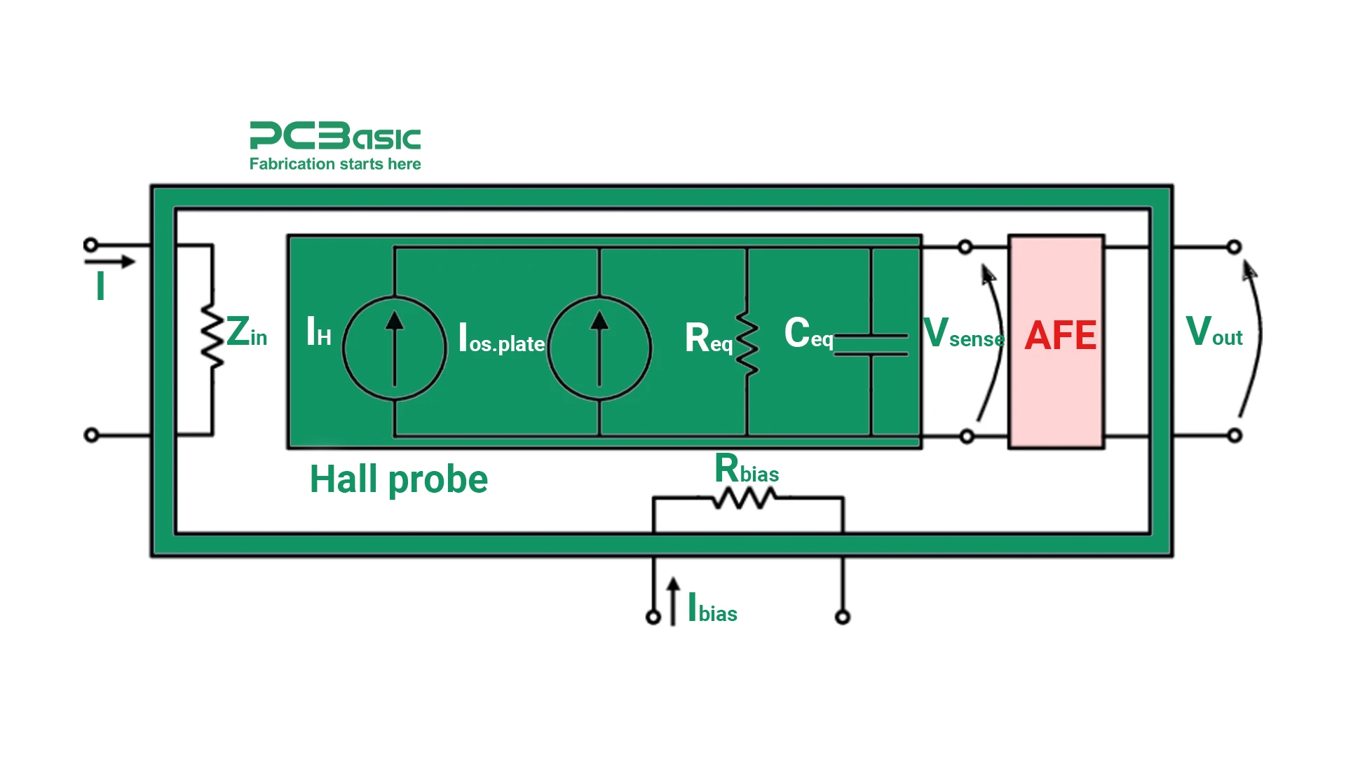
A Hall probe is any device that has the potential to provide force and direction of the magnetic field to be measured. The simplest of these is made of a thin strip of conductive material in which the Hall Effect takes place. While the Hall Effect sensor is an integrated component that functions in systems, the Hall probe is typically a single gadget utilized for measurement. Altogether, both work depending on the same concept of generating voltage changes to measure magnetic fields.
How Hall Probes Are Used in Conjunction with Hall Effect Sensors?
Hall probes are widely employed in laboratories and industrial structures to assess the Hall Effect sensor's functionality. They assist in setting the sensitivity of the sensor since they enable the determination of the precise strength of the magnetic field sensed. This makes certain that the sensor operates optimally within the required application area. Hall probes are most useful where accurate measurements of the magnetic field strength are important, such as in research work or in precise machines.
Here are the practical aspects of wiring and connecting these sensors for optimal performance.
In many cases, the wiring of a Hall effect sensor properly is of paramount importance. Essentially a straightforward wiring diagram may contain the power source connection, the ground connection as well as the output signal connection.

Unlike normal switch hall effect sensor output low (almost 0 volt) when detect magnetic field.
● Connecting the sensor to a Power Supply: A Vcc pin is used to connect the sensor to the power supply terminal or more specifically to its positive pole. The Ground pin is for the negative terminals. This configuration supplies the required voltage to the sensor as long as it is used in this circuit.
● Connecting the Output Signal to the Processing Unit: The output pin of the sensor has an interface to a microcontroller or processor for further processing of the signal. This connection enables the system to produce a response regarding transformation in the magnetic field sensed by the sensor.
The Hall effect sensors have three-pin and four-pin types, the wiring constraints of which differ in some ways.
● 3-Pin Sensors: These again usually have Vcc, ground, and output pin. The wiring is straightforward: To connect, Vcc should be connected to power while Ground should be connected to the negative end, and; Output is connected to the processing unit.
● 4-Pin Sensors: These sensors often have connection apart from the Vcc and Ground along the Output pin of these sensors may have another pin for Analog output or any other operational function. The extra pin can be connected as per the need of applications such as the data requirement and control over other circuits.
Hall effect sensors are used in numerous capacities in many industries due to their high versatility. They are so useful because they can detect magnetic fields, being used in ordinary products and in specific devices.
● Automotive Applications: These types of Hall Effect sensors, in particular, are often used in cars because they are accurate and dependable. They are also used as sensors in tracking the RPM in engines, thus playing the role of ensuring engines run smoothly. They are also applied in position sensing applications such as throttle control, gear shifter and Anti Locking Braking System (ABS). Because they can perform their role under extreme conditions, they excel in automotive applications.
● Industrial Applications: In industrial applications, Hall Effect sensors are used in current measurement for the monitoring of the electrical circuits. They are also applied in the proximity sensing of objects in the production line to check on their presence or displacement. Automation requires these sensors to guarantee the safety and proper functioning of any process.
● Consumer Electronics: Hall Effect sensors are widely used in home electronics. These sensors are used in smartphones and laptops with magnetic switches such as those used to indicate when a screen cover is closed. They are also incorporated in rotation sensors in smartwatches and gaming controllers among others in providing control and feedback.
Hall Effect sensors are extremely flexible elements that can be used in automotive, industrial, and consumer electronics. It is characterized by accurate, durable, and flexible properties, which makes them crucial in present-day technology. Whether the user is designing his home automation system or the control system for a factory, being familiar with Hall Effect sensors as well as the pinouts for the sensors will greatly benefit a user's project. This paper discusses their functions and applications to fully exploit their true potential in design thinking.

Assembly Enquiry
Instant Quote
Phone contact

+86-755-27218592
In addition, we've prepared a Help Center. We recommend checking it before reaching out, as your question and its answer may already be clearly explained there.
Wechat Support

In addition, we've prepared a Help Center. We recommend checking it before reaching out, as your question and its answer may already be clearly explained there.
WhatsApp Support

In addition, we've prepared a Help Center. We recommend checking it before reaching out, as your question and its answer may already be clearly explained there.
