Global high-mix volume high-speed PCBA manufacturer
9:00 -18:00, Mon. - Fri. (GMT+8)
9:00 -12:00, Sat. (GMT+8)
(Except Chinese public holidays)
Global high-mix volume high-speed PCBA manufacturer
9:00 -18:00, Mon. - Fri. (GMT+8)
9:00 -12:00, Sat. (GMT+8)
(Except Chinese public holidays)
HomePage > Blog > Knowledge Base > PTFE PCB: Material Characteristics, Performance, and Manufacturing Options
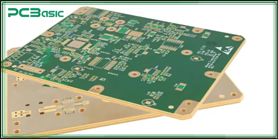
A PCB Multilayer material called Teflon, also known as PTFE (Polytetrafluoroethylene), is exceptional for thermal and electrical properties with a low dielectric constant (Dk ~2.1), making it low in signal loss, which performs very well at high frequencies. This makes them ideal for RF and microwave applications as well as 5G technologies. Compared to FR4 substrates, PTFE excels in harsh environments, which is due to its inert chemical properties, thermal stability, and moisture resistance. Due to the specialized manufacturing process, the cost is high for the fabrication of PTFE PCB. Any mission-critical application where reliability and precision are paramount use of PTFE PCBs is a necessity.
PTFE, the most known as Teflon PCB, is a high-performance PCB laminate material that is often used in applications that require high performance. PTFE PCBs are very popular for high-frequency and high-speed circuits due to their excellent electrical properties with low dielectric constant and low signal loss.
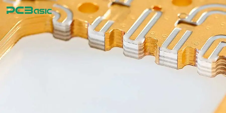
PFA fluoropolymer has remarkable thermal stability, chemical inertness, and low friction. PTFE laminates are widely used in PCB manufacturing and excel in many applications such as RF (Radio Frequency), microwaves, aerospace, and high-speed digital where signal integrity is paramount.
· RF & Microwave Circuits.
· Aerospace & Defense.
· Digital PCBs for high speed (low latency, insignificant signal distortion).
· Medical & Automotive Electronics (harsh environment usage reliability).
What is FR4 PCB Material?
FR4 is the most widely used PCB substrate, consisting of woven fiberglass cloth with an epoxy resin binder. It has good mechanical strength, and is low-cost and readily manufactured, which makes it ideal for general electronic applications.
· Dielectric Constant (Dk): ~4.3 to 4.8 (depends on frequency and temperature).
· Dissipation Factor (Df): ~0.02 (greater than that of PTFE, causing greater loss of signal frequencies).
· Insulation Resistance: Very High (inhibits leakage between traces).
· Breakdown Voltage: 10-20 kV/mm.
· High Rigidity & Strength: Fiberglass-reinforced, so it is excellent for standard PCB use.
· Dimensional Stability: Average (could distort somewhat in high heat or moisture).
· Drill ability: Easier to machine than PTFE which supports the cost-effective fabrication.
· Glass Transition Temperature (Tg) [°C]: 130°C to 180°C (FR4 130°C, high-Tg FR4 ~180°C).
· Thermal Conductivity: Low (~0.3 W/m·K) which means it doesn’t get rid of heat very well (high-power circuits need thermal vias or a heatsinks).
· Flame Resistance: UL94 V-0 rated, self-extinguishing to prevent flame spread.
· Moisture Absorption: 0.1% – 0.3% (greater than PTFE, may impair performance in humid environments).
· Chemical Resistance: Resistant to most solvents, acids and alkalis, but degrades on long term UV exposure.
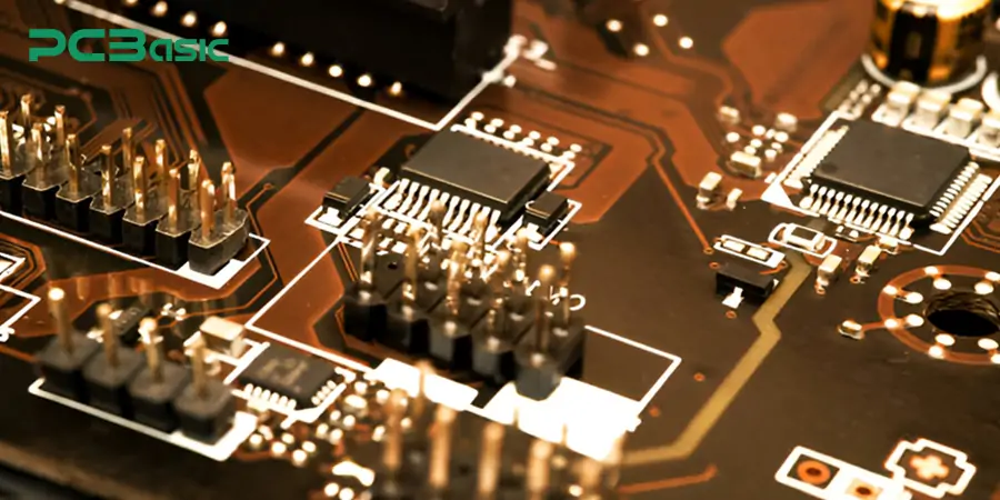
PTFE laminates are engineered PCB substrate materials that cater to high-frequency and advanced high-speed designs. Compared to FR4, PTFE provides a stable dielectric constant, low dissipation factor, and commercially available PTFE also provides good thermal resistance.
· Low signal loss.
· Stable dielectric constant (stable performance over frequencies).
· Good thermal and chemical resistance (aids survival in harsh environments).
· Moisture resistance (prevents degradation of performance).
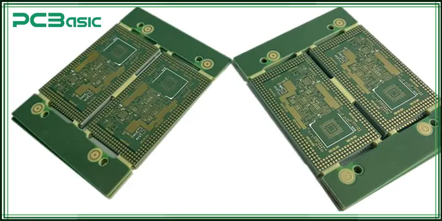
When it comes to PCB materials, perhaps one of the most important properties relating to high-frequency, RF, and high-speed digital designs is the dielectric constant (Dk or εᵣ). Here’s the full story on Dk comparison between PTFE (Teflon) and FR4 and how they affect PCB performance.
|
Property |
PTFE (Teflon PCB) |
FR4 PCB |
|
Typical Dk (1 MHz - 10 GHz) |
2.1 ± 0.04 |
4.3 - 4.8 |
|
Dk Stability vs Frequency |
Nearly flat (minimal change) |
Increases slightly with frequency |
|
Dk Stability vs Temperature |
Very stable (low variation) |
Temperature shift changes |
|
Cost |
Expensive |
Affordable |
|
Applications |
RF, microwave, aerospace |
Consumer electronics |
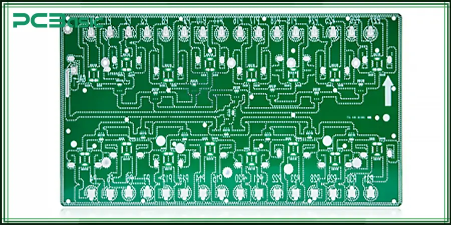
PTFE (Polytetrafluoroethylene) PCBs provide unparalleled electrical performance, material stability, and environmental robustness, making them a go-to dielectrics in the high-frequency and high-performance electronics arena. The very low dielectric loss is one of the most excellent advantages of PTFE PCBs. Signal loss is critical in RF and microwave circuits and impacts performance and range. With PTFE, this loss is minimized; as a result, with high-frequency signals, degradation is reduced.
The Dk of a PCB material plays an important part in how signals propagate through the board. Ensuring uniformity in the dielectric constant guarantees consistent wave propagation and impedance matching, which are critical for timing precision. SPTFE’s stable dielectric properties over every condition provide engineers with the ability to design circuits that will perform reliably across multiple operating conditions including temperature extremes.
Because of its electrical and mechanical properties, PTFE is a no-brainer for critical industries like aerospace, military and advanced communications. PTFE enhances signal integrity in radar and RF modules by minimizing signal reflection and phase shift. It’s also a favorite in satellite and space electronics where performance has to be stable over long periods of time in unpredictable environments. Not only is its use advantageous in these sectors, it is frequently crucial in fulfilling regulatory and technical performance criteria.
Due to the much lower thermal expansion rates of PTFE PCBs, they maintain their dimensional stability even with rapid temperature changes associated with aerospace and industrial environments compared with other types of materials. This prevents mechanical stress, or misalignment of the layers. PTFE’s exceptional chemical and moisture resistance further guarantees long-lasting performance, even in corrosive or high-humidity environments, making it a perfect choice for marine, outdoor, and chemically intensive applications.
PTFE is ideal in scenarios with varying thermal extremes; it consistently maintains its physical or electrical properties from cryogenic lows to extremes at high end of spectrum. This makes it a suitable choice for electronics in extreme thermal environments including avionics, military and spaceborne systems. It also resists reliably in radiation-filled or high-vibration environments where other materials might fail. Furthermore, the low friction, high performance, reliability, and endurance of PTFE in mission-critical systems are due to its low rate of thermal degradation over time.
Considerations in Designing a PTFE PCB
The following are some considerations that need to be followed when designing a PTFE PCB:
· PTFE is less hard than FR4, so care needs to be taken not to dental the surface when it is drilled and engineered.
· Manufacturing Requirements for Specific Needs
· High-resolution Laser drilling for symmetric via formation
· Plating processes that are specialized (like plasma treatment for increased adhesion).
· High temp solder techniques required.
· ENIG is widely used.
Cost Comparison: PTFE vs FR4
· PTFE PCBs cost on average 3–5x more expensive than FR4
· Made for high-frequency and mission-critical applications
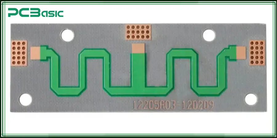
The following are the PCB material suppliers:
· Rogers Corporation (RO3003, RO4350B – rogers PCB).
· Taconic (TLX, TLY series).
· Arlon (AD series).
· Isola (IS680, Astra MT77).
· Essential for high performance: Specialized suppliers.
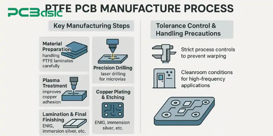
Due to the unique properties of PTFE, producing PCBs from this material requires specialized processes and tools. Unlike other solid substrates such as FR4, PTFE is soft, highly chemically inert, and requires that manufacturers follow highly controlled processes to match the performance, precision, and reliability expectations of OEMs for the finished product.
PTFE laminates are sensitive to mechanical strain and dimensional instability, so they have to be worked carefully. PTFE is not a standard material, nor is it rigid, and if PTFE is not adequately supported during processing, it can stretch or otherwise warp.
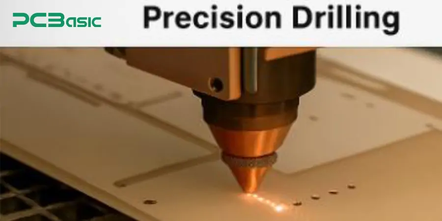
Drilling through PTFE materials has challenges, as they are relatively soft and tend to deform under pressure. To solve this, manufacturers typically employ laser drilling or individual micro-drill bits, creating clean, precise holes even in high-density interconnects (HDI).
Due to PTFE's low surface energy, it does not bond well to anything, even copper during metallization. In order to facilitate the adhesion of copper, a plasma treatment process is used following the drilling process. In doing so, it chemically modifies the PTFE surface on a microscopic level by roughening it up and allowing for more reliable adhesion from the subsequent metal plating.
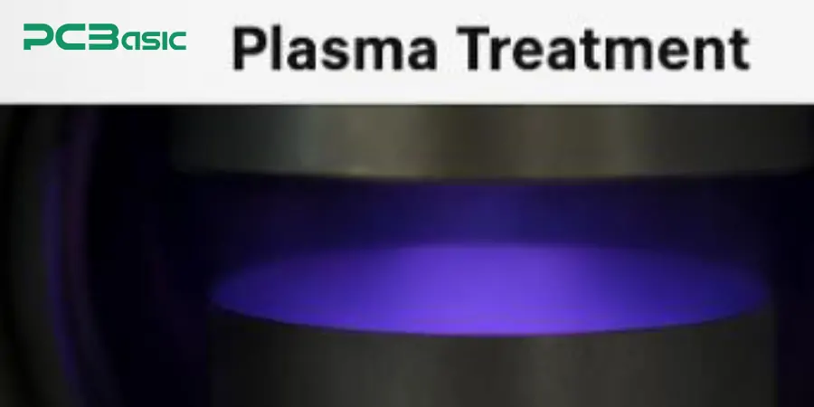
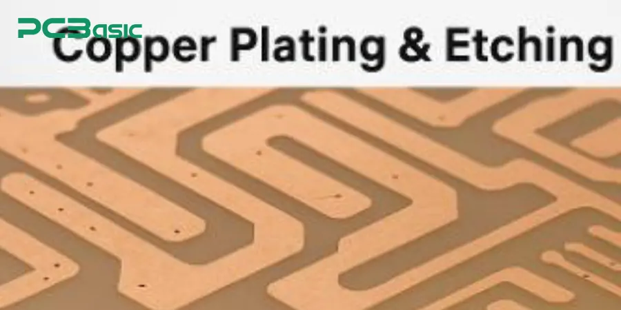
Afterward, the surface treatment is followed by the copper plating, a conductive layer of copper is deposited over the whole board as well as on the drilled vias. Next comes the etching, a very controlled process that creates the fine circuitry by eliminating excess copper.
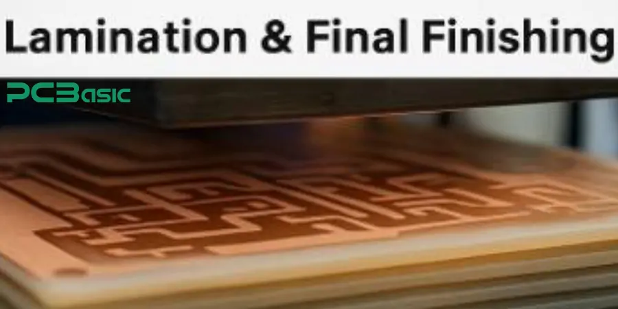
Then, after the plating and etching steps, several layers are laminated together at high temperature and pressure to make a solid multilayer PTFE PCB. Finally, treatment of surface finishes, such as ENIG (Electroless Nickel Immersion Gold) or immersion silver, for example, which offer superb solderability and corrosion resistance, both critical to high reliance applications.
The complete process requires accurate tolerance control. Manufacturers use stringent temperature control, custom tooling, and tightly controlled lamination pressure to mitigate this. Often, PTFE PCBs will be manufactured using cleanroom fabrication capabilities too, to negate any chances of contamination and to maintain any performance needed in the high-frequency and precision RF spaces.
The selection of PTFE (Teflon) or FR4 PCB Materials is ultimately dependent on the frequency, performance and budget limits of your application. With an ultra-low dielectric constant (Dk ~2.1), negligible signal loss, and outstanding thermal stability, PTFE is the perfect substrate for high-frequency RF, 5G, aerospace, and high-speed digital circuits when signal integrity is paramount. Still, given its relatively higher cost and more specialized manufacturing requirements, if the application in question is low-frequency or cost-sensitive, FR4’s price-point and satisfactory performance will still make it the go-to performer. When choosing between these two types of materials make sure to always take into account the frequency range you are working with, the environment, and your budget as to not waste resources on approaches that may be unnecessary for your needs.
Assembly Enquiry
Instant Quote
Phone contact

+86-755-27218592
In addition, we've prepared a Help Center. We recommend checking it before reaching out, as your question and its answer may already be clearly explained there.
Wechat Support

In addition, we've prepared a Help Center. We recommend checking it before reaching out, as your question and its answer may already be clearly explained there.
WhatsApp Support

In addition, we've prepared a Help Center. We recommend checking it before reaching out, as your question and its answer may already be clearly explained there.
