Global high-mix volume high-speed PCBA manufacturer
9:00 -18:00, Mon. - Fri. (GMT+8)
9:00 -12:00, Sat. (GMT+8)
(Except Chinese public holidays)
Global high-mix volume high-speed PCBA manufacturer
9:00 -18:00, Mon. - Fri. (GMT+8)
9:00 -12:00, Sat. (GMT+8)
(Except Chinese public holidays)
HomePage > Blog > Knowledge Base > TL072 Pinout: Specifications, Applications, and Usage Guide
The TL072 is one of the low-noise, high-slew-rate operational amplifier ICs that is well-known for its excellent analog signal processing. It has precision and reliability found in configurations of dual op-amps. It is anchored in the cornerstones of audio amplifiers, filters, and oscillators.
Modern electronics have applications for over $8 billion in the worldwide market on op-amps. They are found within many industries, such as telecommunication, automotive systems, and consumer electronics. Among the ones, TL072 has a JFET input with almost no distortion and an especially wide bandwidth.
This guide will take you through the whole TL072 pinout, technical specifications, and various applications. It would be useful to an electronics hobbyist or professional engineer who needs to know how the TL072 works, how it may be used in circuits, and other alternatives in case of need. By the end, you will understand why the TL072 IC pinout is the most used in the field of analog electronics.
Now, let us take a step ahead and find more accurate information about the pinout TL072.
A pinout is simply how the pins are located on an integrated circuit and what they do. Knowing a pinout ensures that components are properly fit into electronic circuits. TL072 is one of the widely used dual operational amplifiers, or op-amps, and its pinout is a guide to the proper application of its capabilities in processing analog signals.
TL072 is an op-amp, especially known for low-noise JFET inputs, high input impedance, and high bandwidth. All these make it a wonderful choice for precision audio applications, active filters, and instrumentation amplifiers. Its universality and reliability in performance result in wide usage in multiple electronics projects and industrial applications.
 About PCBasic
Time is money in your projects – and PCBasic gets it. PCBasic is a PCB assembly company that delivers fast, flawless results every time. Our comprehensive PCB assembly services include expert engineering support at every step, ensuring top quality in every board. As a leading PCB assembly manufacturer, we provide a one-stop solution that streamlines your supply chain. Partner with our advanced PCB prototype factory for quick turnarounds and superior results you can trust.
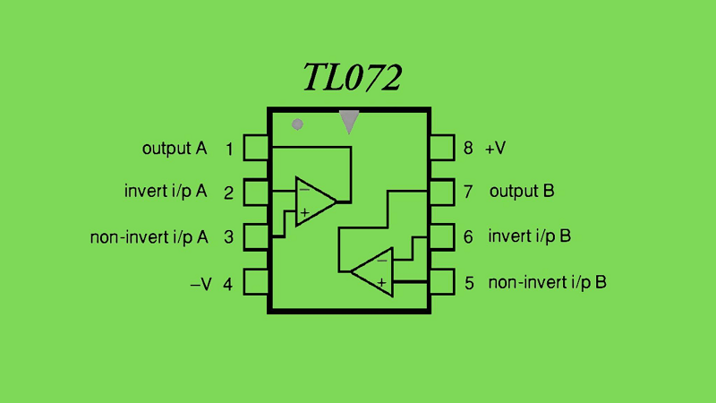
Each pin of the TL072 has a specific function:
1. Pin 1 (Output 1): Output terminal for the first TL072 op-amp pinout.
2. Pin 2 (Inverting Input 1): Inverting input for the first op-amp.
3. Pin 3 (Non-Inverting Input 1): Non-inverting input for the first op-amp.
4. Pin 4 (V-): Negative power supply.
5. Pin 5 (Non-Inverting Input 2): Non-inverting input for the second op-amp.
6. Pin 6 (Inverting Input 2): Inverting input for the second op-amp.
7. Pin 7 (Output 2): Output terminal for the second op-amp.
8. Pin 8 (V+): Positive power supply.

The TL072 can be represented in circuit diagrams with the use of its schematic symbol. It contains two triangular op-amp symbols assigned to pins for the input, output, and power supply.
● Input: The arrows mark the non-invert (+) and invert (-) terminals.
● Outputs: Each triangle has one output line indicating the output terminals.
● Power Supply: The V+ and V- pins are connected to the positive and negative power rails so that they can function correctly.
This symbolic notation simplifies the integration into schematic designs and also allows engineers to see the 'flow of signals' through the IC.
It is popular because of its general-purpose and dual-operational amplifier design. This TL072 has low noise performance and is widely used in many modern-day applications.
The TL072 works very satisfactorily for almost any range of conditions and has impressive input/output characteristics.
The supply voltage operating voltage range ranges from ±3V to ±18V; hence, it can be readjusted to an assortment of circuit schemes. Moreover, the circuit consumes relatively less power and is thus suitable for battery-pumped devices.
For Input/Output Specifications:
● Great input impedance ensures minimal interference signal.
● Low impedance output ensures a good signal.
● Noise and interference suppression requires a high common-mode rejection ratio in the noise and interference suppression. This generally applies to all operations in differential signal processing.
The TL072 provides a high level of reliability with predictable performance in demanding applications.
● Noise Levels: The noise voltage density goes as low as 18 nV/√Hz at 1 kHz to provide clean signal amplification.
● Operating temperature: Very reliable within the range of -40 to +85°C for consumer and industrial applications.
● Slow Rate: The input amplitude of TL072 is tolerated to be very high changes up to 13 V/µs rate.
This TL072 is impressive in that it can function satisfactorily under rather extreme ranges of operating conditions:
● Operating supply voltage range: ±3V to ±18V.
● Input Voltage Range: -15V to +15V w.r.t ground.
● Bandwidth Product: 3 MHz, therefore wholly sufficient for signal processing in the analog system.
● Distortion: Total harmonic distortion is less than 0.01%, which ensures the reproduced signals are very high in accuracy.
The TL072 is rather versatile and reliable, so it's a good starting point for lots of electronic designs.
The TL072 is also used in preamplifiers and other audio circuits with minimal noise in signal amplification, hence amplifying weak signals. The TL072, in active filters, filters signals through low-pass, high-pass, and band-pass filters. In oscillator circuits, the TL072 provides stable waveforms for either timing or clocking purposes.
The TL072 has applications in almost all fields:
● Audio equipment: Amplifiers, mixers, and equalizers demand it due to low noise and distortion.
● Instrumentation systems: Its accuracy makes it well suited for data acquisition and sensor interface circuits.
● Signal Processing: It is essentially used for communication systems and analog filters to condition the signal.
Although TL072 is very popular, sometimes, choices must be made based on availability or specific design requirements. For example, the LM358 is suitable for low-power designs, but its performance is slightly inferior to the TL072, especially in terms of noise and bandwidth. So it is more suitable for less sensitive applications.
For projects with strict budgetary limitations, relatively cheap alternatives like the LM358 should be used. Conversely, more expensive applications needing a better noise performance are aptly served by the premium options, such as the OPA2134.
TL072 Equivalents:
● TL082: Very close equivalent but a bit higher noise level, therefore acceptable for much less critical applications.
● LM358: It consumes less power but at the cost of performance parameters such as noise and bandwidth.
● OPA2134: High-grade op-amp for high-fidelity audio applications.
The TL072, however, balances performance, cost, and availability so that for most general-purpose designs, it's a good choice.

The TL072 operational amplifier can be used in a wide variety of applications and configurations. Probably the most simple and often used configuration is the non-inverting amplifier circuit. In this circuit structure, the input signal is amplified without its phase being altered. This configuration is suited to several applications, including audio processing or signal conditioning.
For instance, in a basic non-inverting amplifier circuit, the input signal is taken to the non-inverting input of the TL072. A feedback loop is completed by attaching a resistor from the output to the inverting input. Another resistor is grounded to the inverting input. The gain of the circuit will be determined by the ratio of these resistors, and you can thus vary the amplification level according to your requirements. A proper power supply setup is important to good performance and is usually a dual supply of ±12V or ±15V. In addition, decoupling capacitors located close to the power pins can greatly reduce noise and stabilize the circuit.
The grounding scheme in wiring the circuit should be carefully considered. One-point grounding with minimal interference, especially in sensitive applications, is recommended. Input and output connections should be short and shielded, as signal loss or noise intrusion are not desirable.
The best practices that must be observed for the TL072 to operate safely for a long time are that it does not overheat since it is easily prevented through proper ventilation and that the IC is not exposed to temperatures beyond the specified range of -40°C to 85°C. For regulated power supplies, the voltage does not fluctuate and, therefore, cannot cause spiking or dipping that can destroy the IC or the functionality of its circuitry.
If problems do arise, the problem-solving should begin with the basics. For example, in a no-output signal situation, first, check if the connections of the power supply are fine and if the input signals lie within their ranges of voltage. Noises or distortions in the signal could indicate grounding problems or that not all the decoupling capacitors are in use. Overheating usually means that the IC is loaded too heavily or the voltages supplied are higher than its rated ones.
Regular maintenance also contributes to the life of your circuit. At times, one should check loose connections and damaged components or corroded contacts and prevent possible problems from becoming worse and getting fixed before. Even protection from power surges through the use of fuses or transient voltage suppression diodes guards the IC.
TL072 is an op-amp with the best balance of performance, reliability, and flexibility. It is characterized by such performance as high input impedance and low noise and is better suited for audio amplification, signal processing, and instrumentation accuracy.
Knowing the pinout TL072, as well as the best practices in circuit design and maintenance, get the best out of it. With proper power supply, grounding, and maintenance, there would be consistency and performance.
Whether you are designing an amplifier, active filter, or oscillator, you are good to go with the TL072 for quality. In case you need further enlightenment on how to add the TL072 to your next project or how to make your PCB design even better, our team of experts is available to help. Your next electronics breakthrough is just one step away!

Assembly Enquiry
Instant Quote
Phone contact

+86-755-27218592
In addition, we've prepared a Help Center. We recommend checking it before reaching out, as your question and its answer may already be clearly explained there.
Wechat Support

In addition, we've prepared a Help Center. We recommend checking it before reaching out, as your question and its answer may already be clearly explained there.
WhatsApp Support

In addition, we've prepared a Help Center. We recommend checking it before reaching out, as your question and its answer may already be clearly explained there.
