Global high-mix volume high-speed PCBA manufacturer
9:00 -18:00, Mon. - Fri. (GMT+8)
9:00 -12:00, Sat. (GMT+8)
(Except Chinese public holidays)
Global high-mix volume high-speed PCBA manufacturer
9:00 -18:00, Mon. - Fri. (GMT+8)
9:00 -12:00, Sat. (GMT+8)
(Except Chinese public holidays)
HomePage > Blog > Knowledge Base > Potentiometer Wiring: A Comprehensive Guide
A potentiometer, also referred to as a pot, is a three-terminal variable resistor that controls voltages, modifies signals, and tunes electronic circuits. Potentiometer applications include a range of tasks from audio-level control switching to dimmer switches and sensor calibration. Potentiometers in these applications provide vital functions in circuit design.
The knowledge of potentiometer wiring is fundamental to ensure the proper operation of the intended functionalities of the potentiometer.
So, let's understand the complete details of how to wire a potentiometer.
The potentiometer, also known as "pot," is a three-terminal variable resistor used to control the operation of electronic devices by the variation of resistance. It is most effectively used for operations such as volume control in sound systems, display brightness control, and tuning of electronic circuits. Potentiometer wiring becomes critical in such applications for doing proper function.
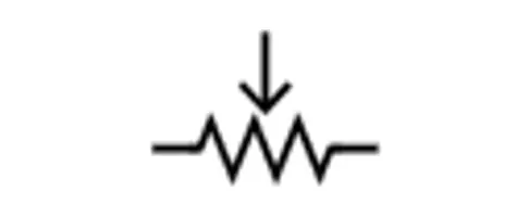
The general symbols show a resistor with an arrow pointing toward the center to represent the movable wiper terminal. This is the typical symbol:
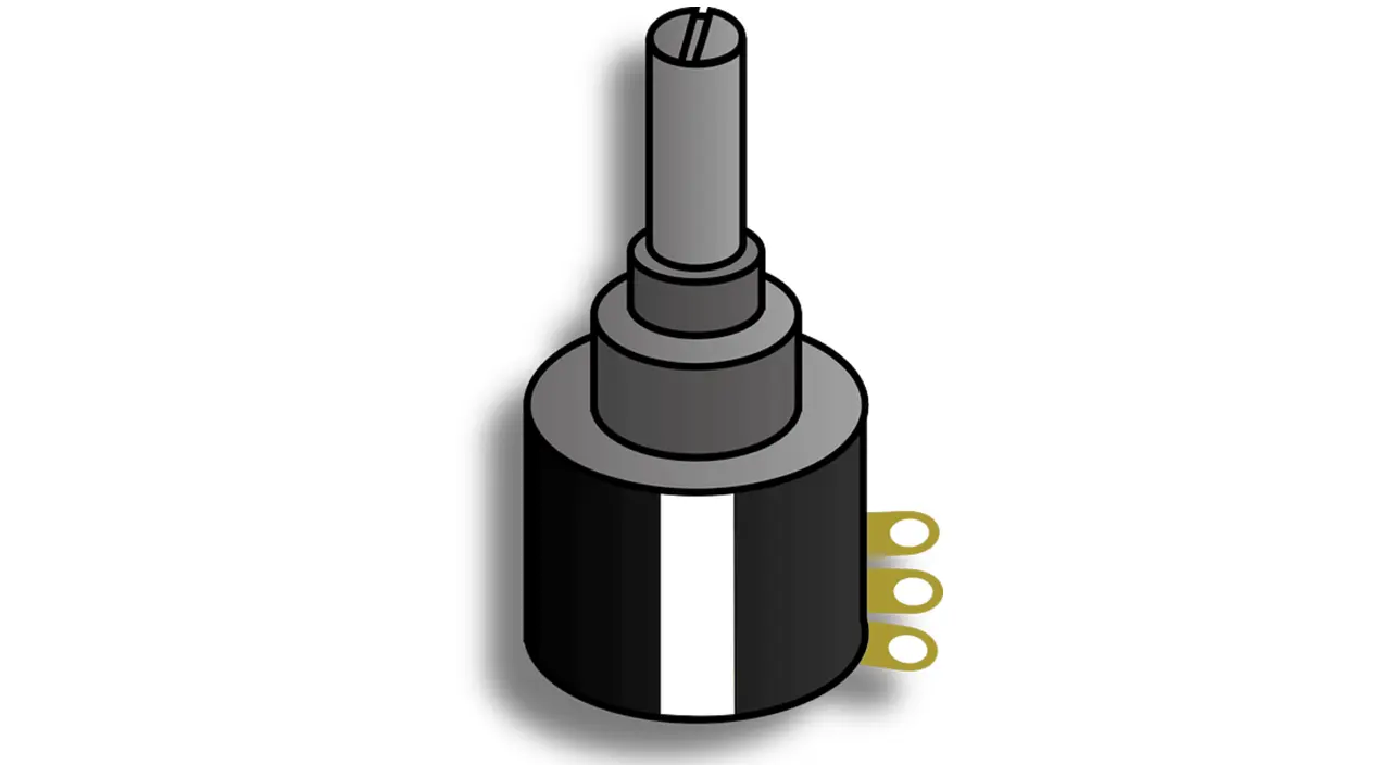
A typical potentiometer consists of three pins:
● Pin 1: Fixed terminal A connected to one end of the resistive track usually connected to VCC (positive voltage).
● Pin 2: Wiper terminal, adjustable middle terminal moving along the resistive track, is used for varying resistance and output voltage.
● Pin 3: Fixed terminal B connected to the other end of the resistive track, which is usually connected to GND (ground).
The output voltage will be defined by the position of the wiper (Pin 2), which acts as a voltage divider between Pin 1 and Pin 3.
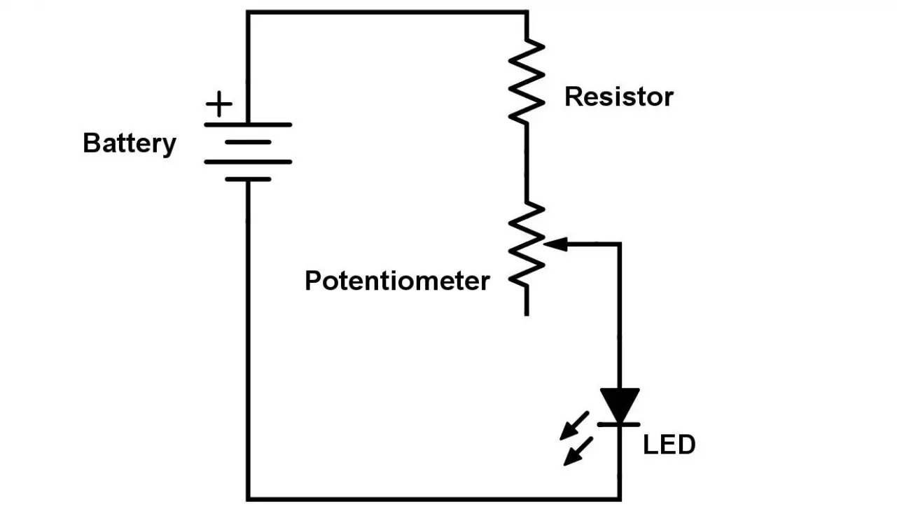
A basic wiring diagram for the potentiometer consists of:
● Voltage source connected to Pin 1
● Ground connected to Pin 3
● The output signal is taken from Pin 2
With this setup, the potentiometer functions as a variable resistor, enabling very fine tuning of Vout.
 About PCBasic
Time is money in your projects – and PCBasic gets it. PCBasic is a PCB assembly company that delivers fast, flawless results every time. Our comprehensive PCB assembly services include expert engineering support at every step, ensuring top quality in every board. As a leading PCB assembly manufacturer, we provide a one-stop solution that streamlines your supply chain. Partner with our advanced PCB prototype factory for quick turnarounds and superior results you can trust.
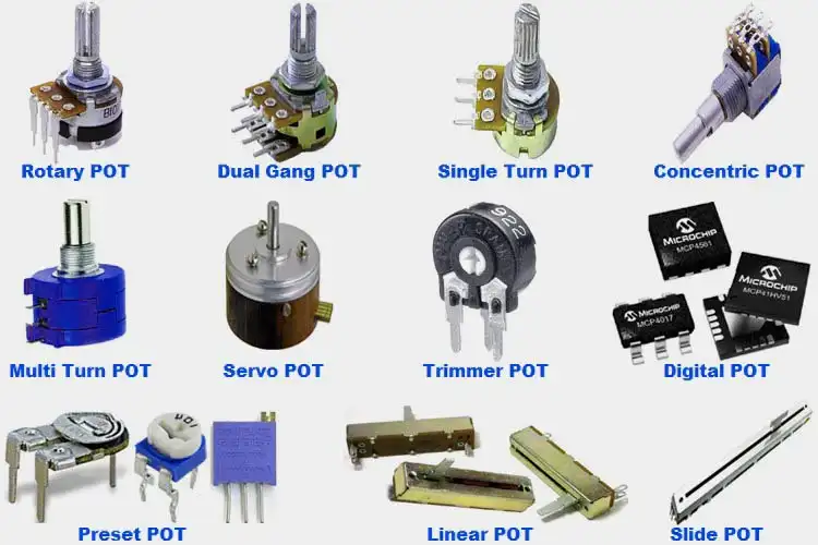
Potentiometers come in various types with certain applications. The key to their differences is their mechanical configuration and the manner in the resistance is variable. Below are the most common types of them all.
Linear potentiometers have a resistive track with a directly proportional change of resistance to the movement of the wiper. In other terms, the output voltage is directly proportional to the wiper position. They are used to implement volume controls, sensors, and position-sensing systems.
Also known as log tapers or log tapers potentiometers, they have a log-type of response curve. It is a case of small quantities at the lower positions having a greater effect while the quantities at the higher positions have minor amounts of change. They are mostly used in applications of audio controls and man-machine applications where the sense of the user is closer to a log response.
These are the most widely used potentiometers with the wiper taking a rotary path about a resistive track. Rotary potentiometers are used within dimmer switches, volume controls, and industrial automation systems. Both the linear and the log types are provided.
Also known simply as fader potentiometers, they have a linear resistive track with the wiper that travels instead of rotating. Used frequently on mixing consoles of the audio sort, light controls, and also within applications of motion control.
These are small variable potentiometers that are implemented to carry out calibration and fine-tune applications. Trimpots are normally mounted on PCB (printed circuit boards) and are driven by a screwdriver. Trimpots are implemented for circuit calibration, sensor calibration, and low-maintenance applications.
Unlike traditional mechanical potentiometers, digital potentiometers (or digipots) do not have a physical wiper but work with the aid of electronic controls. Instead of a wiper, they modify the resistance with the support of built-in ICs (integrated circuits). They are powered by microcontrollers or digital signals.
Each type of potentiometer is specially suited to a specific function, and the proper choice is made according to the requirements of the circuit or device.
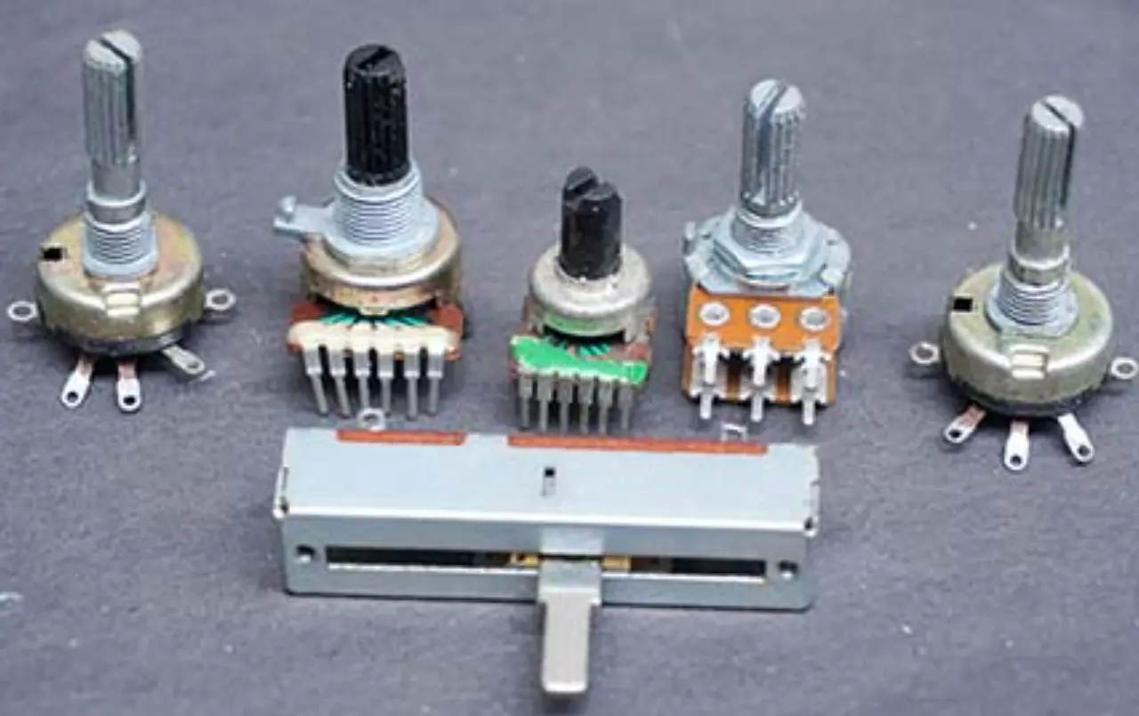
Selecting the correct potentiometer is crucial to supply proper control and durability to the circuit. Different considerations need to be made to choose a potentiometer to fill a specific need.
The resistance value of a potentiometer will also measure the current or voltage that can be controlled by it. Common values include 1kΩ, 10kΩ, 50kΩ, 100kΩ, and others. The right choice depends on the circuit’s requirements:
● Low resistance (1kΩ – 10kΩ): Suitable for current control applications.
● Medium resistance (10kΩ – 100kΩ): Ideal for voltage control and signal processing.
● High resistance (100kΩ – 1MΩ): Used in high-impedance circuits such as audio and sensor applications.
Tolerance indicates the allowable range of deviation of the potentiometer’s nominal value of resistance. Common tolerances are between ±5% to ±20%. The lower the tolerance is, the greater the precision is, which is desirable in calibration networks and measurement instruments.
A power rating indicates how much power a potentiometer can dissipate without overheating or degradation. Common ratings range between 0.1W to 2W or higher. For audio control applications where currents are low, a potentiometer with either 0.25W or 0.5W is fine; other applications with higher power should call for more sturdy potentiometers.
The application will specify whether a rotary, digital, slide, trimmer, log, or linear potentiometer is the best solution. For example:
● Audio applications → Logarithmic potentiometer
● Precise calibration → Trimpot
● Automated control systems → Digital potentiometer
● User-interface controls → Rotary or slide potentiometer
Potentiometers come in a variety of sizes and form factors. The specification, therefore, depends on available physical space on the PCB or for panel-mounted designs. While larger versions can handle fairly high power, they are not suitable for designs where size is at a premium.
Potentiometers can be mounted in different ways depending on the circuit design:
● Through-Hole Mounting (THM): Suitable for PCB designs that call for strong mechanical support.
● Surface-Mount Technology (SMT): Used on small automated runs.
● Panel-Mounting: Designed to house external user controls such as volume controls and dimmer switches.
By considering these factors, you can ensure that the selected potentiometer meets your application’s electrical, mechanical, and operational requirements.
Wiring is essential to the functioning of a potentiometer since the type of potentiometer and its application dictate the wiring arrangements. Typical wiring arrangements for various types of potentiometers are shown just below:
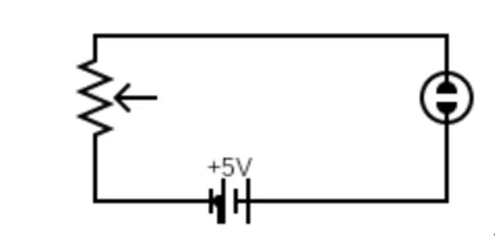
A linear potentiometer is predominantly used in the application as a voltage divider controlling voltage output. Therefore, the wiring will be:
● Pin 1: Connect the Power Circuit (VCC or Positive Voltage)
● Pin 2(Wiper Terminal): output variable voltage depending on the position of the wiper.
● Pin 3: earth to ground (GND).
Example Application: Volume control, sensor adjustments.
A logarithmic potentiometer is widely used in audio circuits where sound perception follows a logarithmic scale. Wiring is quite similar to a linear potentiometer:
● Pin 1: Connected to VCC.
● Pin 2: Provides output voltage (variable signal).
● Pin 3: Connected to ground.
Example Application: Audio volume controls, tone adjustments.
● Multi-Turn Potentiometer: Required for high accuracy resistance adjustments. Mainly intended for calibration circuits. Connection is like a linear potentiometer but very fine adjustment range in resistance variation can be done.
● Slide Potentiometer: It has kind of same working as rotary potentiometer but its mechanism is actually based on sliding instead of a rotating knob. It follows the same wiring principle as linear potentiometers.
Example Applications: Audio mixing consoles for slide potentiometer, fine-tuned sensors for multi-turn potentiometer.
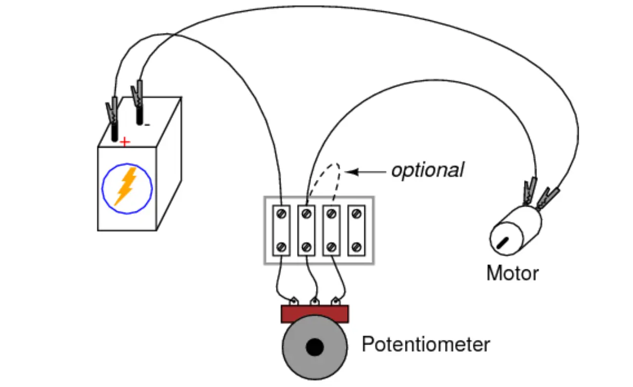
Wiring a potentiometer correctly ensures it functions as it is supposed to work whether it a variable resistor (rheostat) or voltage divider. The procedure of wiring differs depending on the use of the potentiometer in a circuit.
Stepwise Wiring Guide on Using Potentiometer:
● Pin 1 (Fixed Terminal A) → Connected to VCC (positive voltage).
● Pin 2 (Wiper Terminal) → Provides the adjustable output voltage.
● Pin 3 (Fixed Terminal B) → Connected to GND (ground).
A potentiometer may be connected in two basic settings:
This setup provides an adjustable output voltage:
● Pin 1 → Connect to VCC (+5V, +12V, etc.).
● Pin 3 → Connect to GND.
● Pin 2 (Wiper) → Provides a variable voltage output.
In this mode, the potentiometer acts as a variable resistor by using only two terminals:
● Pin 1 → Connect to VCC.
● Pin 2 (Wiper) → Connect to the load.
● Pin 3 is left unconnected.
Connect terminals through soldering or jumper wire to a breadboard, PCB, or control panel. Proper wire insulation to avoid accidental short circuits.
● Read resistance or voltage fluctuation with a multimeter while turning or sliding the potentiometer.
● It must be a smooth transition devoid of all the jumps as output volts or resistance changes.
With minimal hassle and complete precision, these steps will put a potentiometer into a circuit.
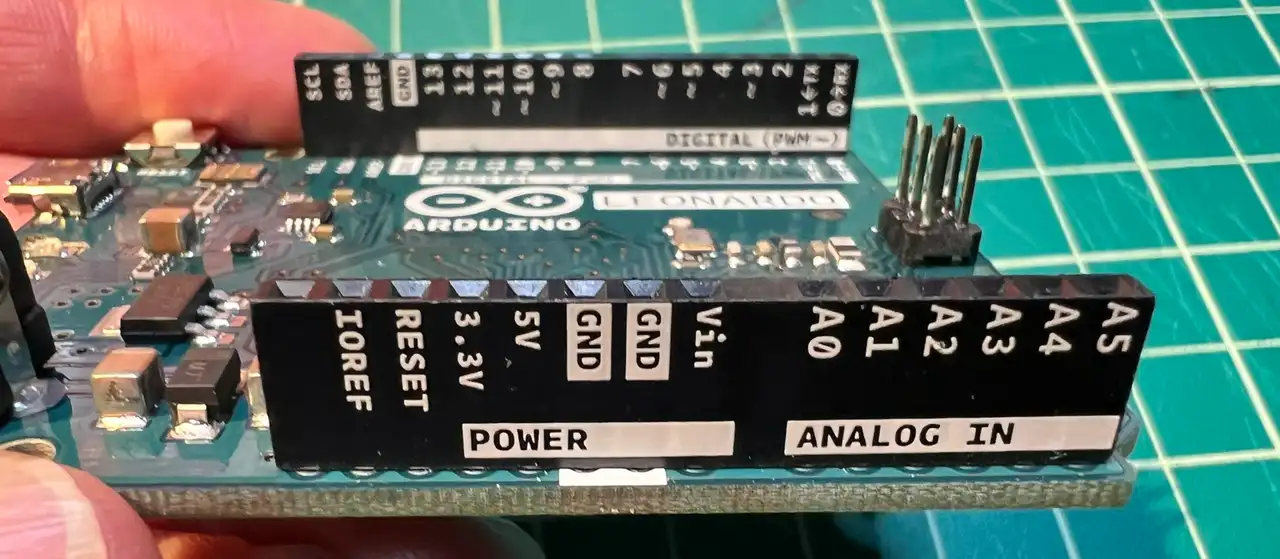
Potentiometers are versatile components that can be used in advanced wiring configurations to attain specific functionalities. Let us look into advanced wiring configurations and applications.
Shielded potentiometer wiring is found to be used in an environment where EMI or RFI affects the quality of the signal. The shield, basically a conductive material, surrounds the wiring and acts as a barrier to prevent external noise from interfering with the signal. This kind of wiring is extensively used in high-fidelity audio and sensitive measurements.
Dual gang potentiometers are two potentiometers on a common shaft (or knob) to be controlled simultaneously. They are installed in stereo audio systems to be used to simultaneously control both the left and right channels.
In industrial controls, these dual-gang potentiometers are found wherever multiple circuits must be adjusted synchronically.
These are taper potentiometers, either logarithmic or audio taper pots, which exhibit non-linear response characteristics. They find their main application in audio systems such as volume control, wherein the human ear perceives variation in sound intensity logarithmically.
Trimmer potentiometers, or trimpots, consist of a tiny but adjustable potentiometer for fine adjustment or calibration inside an electronic circuit. Most of them have been mounted directly onto PCB and adjusted by using a screwdriver. Trimpots find common use in power supplies, oscillators, and sensor calibration circuits.
Potentiometer splitters are used for splitting a single potentiometer's output into several signals. This method is useful in cases like multi-channel audio mixers or lighting control, where a single controller must adjust the operation of several different circuits in unison.
Digital potentiometers or digi pots are electronically controlled devices replicating conventional manual potentiometers but adjusted with digital signals for use in automated systems, microcontrollers, and digital circuits where precise, programmable control is required. Such cases make them suitable for environments wherein manual adjustment is impractical or impossible to execute.
Potentiometers are electronic component objects widely used in voltage, resistance, and signal level adjustment in an admirable variety of electronic circuits. Their proper understanding of wiring and applications is the key to precision control in audio, sensor, lighting systems, and industrial automation applications.
Potentiometer types, from basic voltage divider configurations to complicated digital potentiometer wiring, imply that proper choice and wiring make for optimum performance. Circuit functionality and efficiency can be enhanced by applying best wiring practices.
Before selecting a potentiometer you must consider factors like Resistance value, power rating, taper type, and mounting style.

Assembly Enquiry
Instant Quote
Phone contact

+86-755-27218592
In addition, we've prepared a Help Center. We recommend checking it before reaching out, as your question and its answer may already be clearly explained there.
Wechat Support

In addition, we've prepared a Help Center. We recommend checking it before reaching out, as your question and its answer may already be clearly explained there.
WhatsApp Support

In addition, we've prepared a Help Center. We recommend checking it before reaching out, as your question and its answer may already be clearly explained there.
