Global high-mix volume high-speed PCBA manufacturer
9:00 -18:00, Mon. - Fri. (GMT+8)
9:00 -12:00, Sat. (GMT+8)
(Except Chinese public holidays)
Global high-mix volume high-speed PCBA manufacturer
9:00 -18:00, Mon. - Fri. (GMT+8)
9:00 -12:00, Sat. (GMT+8)
(Except Chinese public holidays)
HomePage > Blog > Knowledge Base > Overview of an SPDT Switch
In electronic circuits, switches play an important role by controlling the flow of signals or power. Single Pole Double Throw (SPDT) switch is a type of switch that has one input (Single Pole) and two output terminals (Double Throw). As the name suggests, SPDT can switch the input signal between two output terminals.
The functionality of SPDT can be explained with an example of light and fan. When the input is ON, the power is delivered to either output terminal to switch between light and fan. SPDT switch can be used to control the direction of the DC motor by changing the polarity of the power source, either clockwise or anticlockwise. SPDT switches are one of the most common types of switches used in electronic circuits due to their versatility and extensive use in household and industrial applications.

Figure 1: SPDT Switch symbol and industrial SPDT switch
The SPDT stands for Single Pole Double Throw switch. SPDT switch is an electrical switch that is often used in electronic circuits to control the flow of signal or for toggling the signal. The SPDT switch has one input terminal and two output terminals. The basic purpose of this type of switch is to toggle the input between two output terminals. In sensitive electronic circuits, SPDT switches are used as a safety switch. When the circuit draws current above the specified limit, the SPDT switch cuts the power source by toggling the output terminal.
The SPDT switch is more versatile as compared to the SPST (Single
Pole Single Throw) switch due to its unique feature of connecting the input
between either of two output terminals. Unlike an SPST switch that can only
connect or disconnect one circuit at a time. To toggle the input between two
output terminals, the SPDT switch has a common terminal (Input), a Normally
Open Terminal (connected to a power supply), and a Normally Close Terminal (connected
to load). The Basic symbol of SPDT and industrial standard SPDT switch is shown
in Figure below.
Understanding SPDT switch circuit components is important for engineers to properly use them in different electronic circuit applications. An internal circuit of SPDT switch consists of a metal lever, an actuator, one input terminal, and two output terminals.
1. Metal Lever: The movable contact of a lever is connected to the actuator.
2. Actuator: The actuator works as a knob that shifts the electrical connection between two output terminals of the SPDT switch. The two terminals are known as NO and NC.
3. Common Terminal: The input of the SPDT switch is known as the common terminal. The power source is applied at this terminal of the SPDT switch such as the data line or voltage. This terminal of the SPDT switch is always connected with either the NO or NC terminal of the switch. It acts as a main controller that controls the flow of current between two output terminals of the SPDT switch, i.e., NO and NC.
4. Normally Open Terminal (NO): This terminal is known as a ‘Normally Open’ switch. In the default scenario, this terminal is not connected with the common terminal of SPDT switch. When the switch or button is pressed, it makes connection with common terminal allowing the signal to flow.
5. Normally Close Terminal (NC): This terminal is known as the ‘Normally Closed’ terminal. In default scenario, the NC terminal is connected with the common terminal of SPDT switch. When the switch or button is pressed, it disconnects the NC terminal from common terminal. For example, in fire alarm and safety circuits, the circuit is active constantly until the sensor senses the smoke and toggles the power source to alarm.
The working operation of an SPDT switch is pretty straightforward. The working of an SPDT switch can be understood from its basic circuit, as shown below.

Figure 2: Basic circuit structure of SPDT Switch
In default situation, the common terminal is connected with the NC terminal allowing the power to travel through Load 1. When the SPDT switch is pressed or toggled, the common terminal will get connected with the NO terminal allowing the power to travel Throw Load 2.
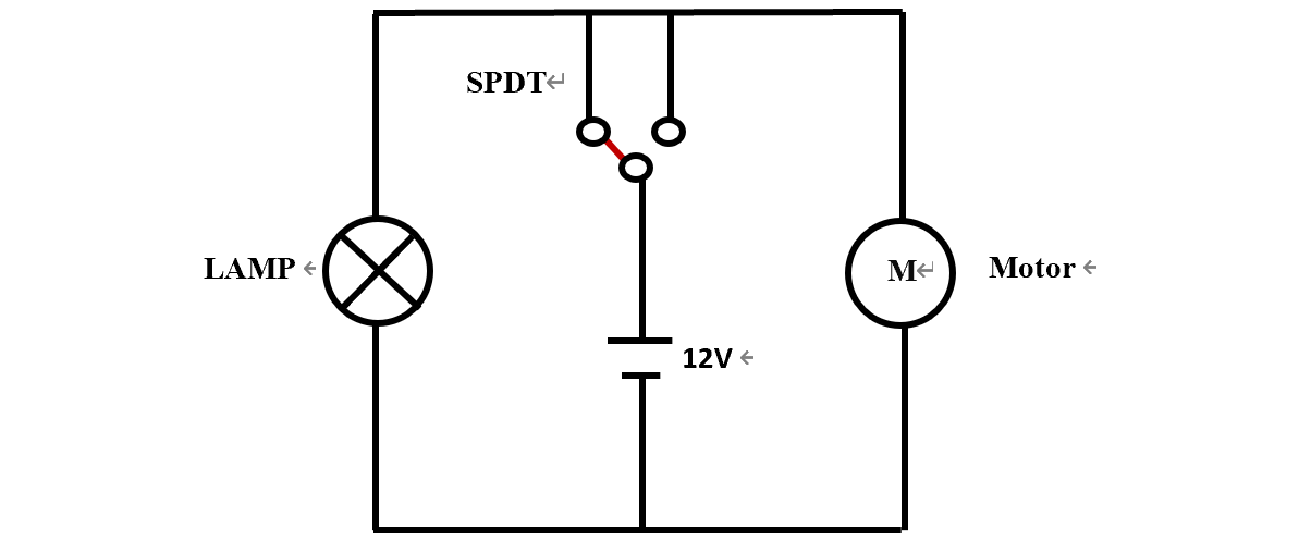
Toggle switches are vital components in
many electronic circuits. A simple illustration of Single Pole Double Throw switch
is shown in Figure 3. The SPDT switch acts as a bridge between two output loads
namely Lamp and Motor. Depending on the SPDT switch condition, either the lamp
will glow or the motor will run. In the diagram, it can be seen that SPDT
switch has two output terminals and one input terminal. The lamp is connected to
NC output terminal and the motor is connected to the NO output terminal.

In the default condition, when the 12V appears on the common terminal of the SPDT switch the lamp will glow as the lamp is connected to the NC terminal. When the toggle switch is pressed, the NO terminal will be connected with the common terminal of the SPDT switch and the motor will turn ON.
SPDT switches are the most common electronic switches used in many applications, including household appliances, consumer electronics, and industrial systems. Some of the most common applications of SPDT switches are:
1. Safety and Power Control Circuits: SPDT switches are widely used in controlling power supplies in many applications. These switches work by toggling the different voltage levels. SPDT switches are often used in fire alarms and emergency shutdown circuits. In electrical industries, the SPDT switch is mostly used as an emergency shutdown switch, where power is cut off in dangerous situations.
2. Relay & Logic Circuits: In digital electronics, SPDT switches are used for implementing binary logic circuits.
3. Motor Control: One famous application of the SPDT switch is controlling the direction of the motor. When implemented in an H-bridge circuit in such a way that it changes the polarity of power supplied to the motor. When the power supply polarity is changed with the help of the SPDT switch, the motor will run in forward and reverse directions. When an SPDT switch is used along with a potentiometer, it can be used to control the speed of the motor.
4. Industrial Control Systems: In many industries, SPDT switches are used to control the operation of multiple devices to ensure smooth operation. For example, when one device is ON, the SPDT switch turns OFF the other device and vice versa.
5. Automation Industry: SPDT switches are also widely used in PLC and SCADA systems for industrial automation. In many applications, SPDT switches are used as limit switches. When some mechanical part hits a certain limit, it stops or alters the motion.
6. Household Applications: SPDT switches are also commonly used in household fans for toggling between different speed levels. They are also used in lighting systems to switch between different lighting patterns.
There are four basic types of switches: SPST, SPDT, DPST, and DPDT. Understanding these switches is of utmost importance for electrical engineers to properly use them in their circuit designs. Pole means number of inputs and Throw means number of outputs. For example, in the SPDT switch, Single Pole means one input and Double Throw.
1. SPST (Single Pole Single Throw)
Single Pole Single Throw is the simplest type of switch. SPST switch has only one input and one output terminal. When the switch is ON, it establishes a connection, and when it is OFF, it breaks the connection. The light or fan in the room uses an SPST switch. When you Turn ON the switch, it glows a light, and when Turn OFF a switch it OFF the light.

2. SPDT (Single Pole Double Throw)
SPDT switch as discussed earlier has one input terminal known as the common terminal and two output terminals known as NC and NO. These switches are used to control the flow of current between two output terminals. For example, one power source is used to control either a lamp or motor at a time.

3. DPST (Double Pole Single Throw)
DPST switch is used to turn ON/OFF two circuits simultaneously
using a single actuator e.g. toggle button. DPST has two poles and one throw.
DPST switches are two SPST switches that are built together.

4. DPDT (Double Pole Double Throw)
DPDT Switch has two inputs and four outputs, making it a
six-terminal switch. DPDT switches are designed to control the two circuits using
the same actuator. The advantage of using a DPDT switch is that it can control
two separate circuits independently.

5. SPST VS SPDT VS DPST VS DPDT Comparison
|
Feature |
SPST |
SPDT |
DPST |
DPDT |
|
Number of Poles |
1 circuit |
1 circuit |
2 circuits |
2 circuits |
|
Number of Throws |
1 throw |
2 throws |
1 throw per pole |
2 throws per pole |
|
Advantages |
Simple, reliable, and cost-effective |
Flexibility and efficiency |
Power handling and safety |
Control and customization |
|
Applications |
Home appliances and safety devices |
Consumer electronics and telecommunications |
Heavy machinery and power switches |
Control panels and electrical motors |
To sum up, switches play an important role in controlling electronic circuits. They are used in electronic circuits to control the flow of current between different outputs. Among all, SPDT switches are highly used in electronics due to their flexibility and efficiency. They are extensively used in consumer electronics, industrial automation, and digital electronic applications. Understanding all types of switches is important to properly use them in your electronic circuits.

Assembly Enquiry
Instant Quote
Phone contact

+86-755-27218592
In addition, we've prepared a Help Center. We recommend checking it before reaching out, as your question and its answer may already be clearly explained there.
Wechat Support

In addition, we've prepared a Help Center. We recommend checking it before reaching out, as your question and its answer may already be clearly explained there.
WhatsApp Support

In addition, we've prepared a Help Center. We recommend checking it before reaching out, as your question and its answer may already be clearly explained there.
