Global high-mix volume high-speed PCBA manufacturer
9:00 -18:00, Mon. - Fri. (GMT+8)
9:00 -12:00, Sat. (GMT+8)
(Except Chinese public holidays)
Global high-mix volume high-speed PCBA manufacturer
9:00 -18:00, Mon. - Fri. (GMT+8)
9:00 -12:00, Sat. (GMT+8)
(Except Chinese public holidays)
HomePage > Blog > Knowledge Base > Multimeter Symbols: A Complete Guide!
Do you know how to use multimeter symbols? You'll learn lastly to write V~ for AC, Ω for resistance and A for current. Symbols for better testing are given at each step. We will teach you here how to measure safely. There will be relatively few ambiguous tests on circuits; they will get clear and unambiguous results.
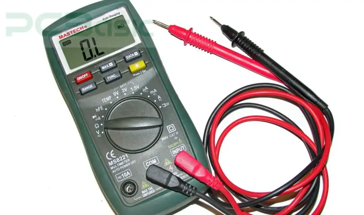
You use a multimeter to measure voltage, current, and resistance. Symbols like V~ and Ω simplify readings. You follow clear instructions by connecting the black lead to COM.
The red lead goes into the VΩ port. You turn the dial to AC (V~), DC (V—), or resistance (Ω). The continuity symbol checks if circuits connect properly. This tool is accurate, insightful, and ensures precise results. You gain an objective overview with its valid and original design.
The units of a multimeter are volts (V), amperes (A), and ohms (Ω). You measure voltage from 0.001V to 1000V. Current is measured in amps (A), ranging from µA to 10A. Resistance spans from 0.1Ω to 50MΩ.
You see the dc voltage symbol or ac voltage symbol on the dial. Connect probes to the COM and V/Ω ports. Adjust the scale for proper measurement. Follow calibration to ensure accurate results. Multimeter symbols help you test circuits safely. Use it carefully for reliable applications!
You can see the LCD display displays 4 digits. It reads either in volts (V), amps (A), or ohms (Ω). Some displays include a 2000 count system. Backlights let you read in low light.
During measurements, 'V~' symbols are shown. This display supports detailed data layouts. You don't have to read through any text or have no clue as to what the result is. The design follows a simple, clear framework for learning. Always check the blueprint for advanced display uses.
A 10A fuse protects circuits. Currents greater than 500mA cause a break. Replace fuses with the exact configuration. Fuses are in accordance with safety standards for secure use. The assembly includes ceramic or glass parts. You check the breakdown diagram before replacing it. These ensure no harm to your system. Always check for proper fuse components. This setup keeps your multimeter safe during tests.
You can pick ranges with the dial. The voltage can be V~ for AC or V⎓ for DC. For readings up to 50MΩ, adjust for resistance (Ω). You set current ranges from 20µA to 10A. It also includes advanced models with auto-ranging capability. The design ensures smooth turning for precise functionality. The symbols on the multimeter always apply for choosing mode. This dial simplifies your circuit structure tests. Follow its layout to avoid errors.
Circuits are connected to COM ports and probes. The common ground gets the black probe. Volts (V), ohms (Ω), and amps (A) red probes handle. The PVC covers of PVC encapsulate each probe for insulation.
These handle 10A current symbols safely. Alligator clips or hooks are usable probes. Use the arrangement carefully to prevent shocks. The probes’ composition ensures safe use for tests. Always store probes in a neat setup.
Tools include Min/Max hold function buttons. You press the "Hold" button to lock readings. Record "Min/Max" of fluctuations. Advanced buttons handle range configuration. These controls improve your multimeter's build precision. Use buttons to analyze changing system results. Every button follows a clear framework. Always read the button assembly guide. Check buttons for additional functionality during your setup.
You put probes into the input jacks. Use COM for black probes. Voltage and resistance work on the VΩA jack. These support up to 1000V CAT III. Always test the jack composition for strength. Jacks must match the multimeter setup. Incorrect arrangement can damage your readings. You follow the jack blueprint in the manual.
The ground circuits are safely handled with the COM port. For all measurements, you use it. This connected directly to the black probe. Ensure the port's functionality before every use.
The VΩA input jack makes safe voltage and current handling. If you need to measure up to 50MΩ resistance or 600V CAT II circuits. During testing is must meet all safety standards.
For ranges, you use the auto ranging switch. It is time saving it requires no manual adjustments. For voltage, it is 1mV to 1000V detection. Auto resistance set from 0.1Ω to 50MΩ. You analyze circuits without recalibrating your configuration. This feature improves every test's framework.
9V alkaline batteries are used in the battery compartment. You install batteries following the setup diagram. Proper power is always checked for polarity. 200mAh capacity battery lasts longer. Replace them often to keep this performance. Keep the compartment's design structure secure. Batteries power every critical functionality.
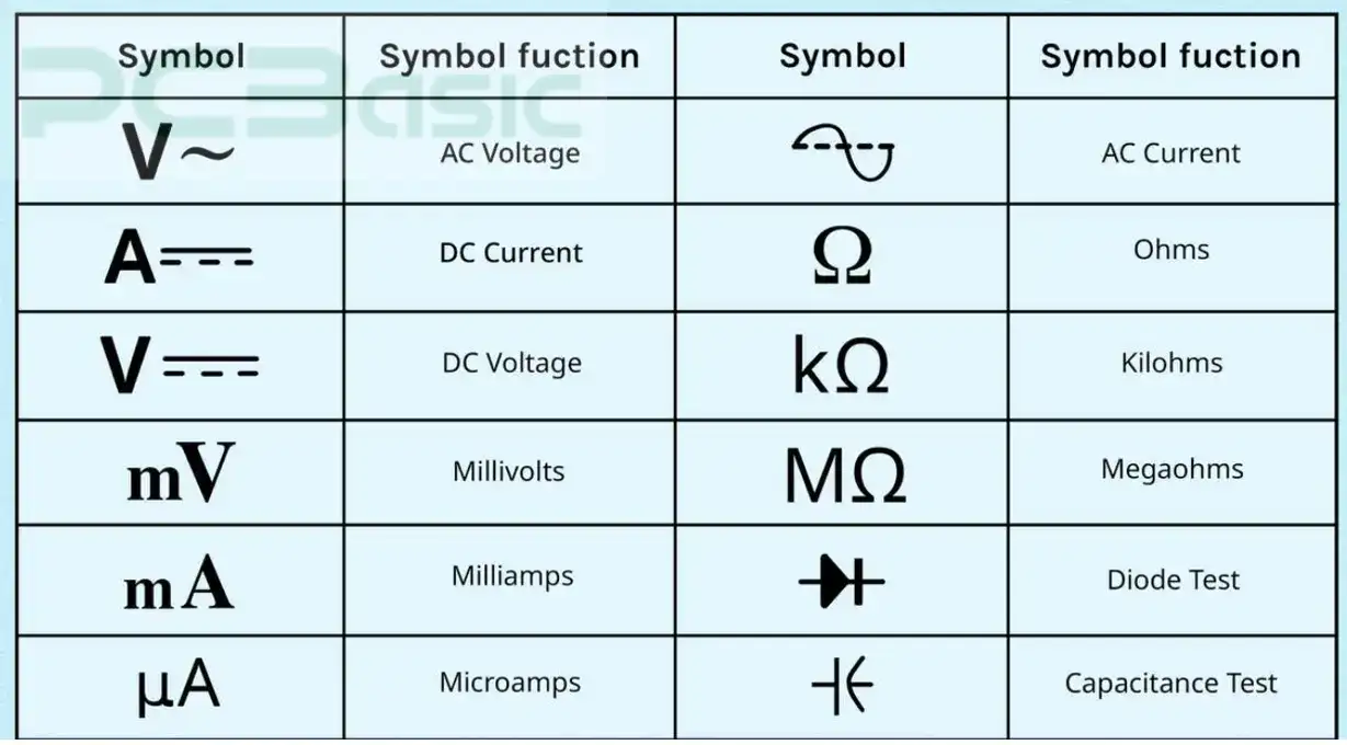
- AC Voltage (V~): This symbol uses to measure the alternating current (AC) voltage. 0V to 750V AC is ideal for household circuits, it is in most multimeters. Make sure you pick a range of 200V or 600V, according to the expected voltage. Probe are with PVC insulation which are connected to the COM and VΩA jacks. Use this measurement in accordance with IEC 61010, for safe use.
- Millivolts (mV): A millivolt is one thousandth of a volt and therefore appropriate for sensitive circuits. In mV mode, multimeters measure the range that includes from 0.1mV up to 500mV, and can help you read out precision devices including sensors. In this case use gold plated probes for low voltage measurements.
- DC Voltage (V⎓): The direct current voltage symbol there is an abbreviation of DC voltage under which you can measure direct current from 0.001V to 1000V DC. Batteries and solar panels are the common uses of it. A true RMS system in a multimeter guarantees accuracy even as a voltage fluctuates.
- AC Current (A~): It is used to measures alternating current (AC) in circuits. For devices out of 10mA to 10A AC, use it. Make sure that 10A fused terminal is correct anchored for safe operation. Measurement meets CAT III safety standards.
- DC Current (A⎓): The direct current, as measured by the DC current symbol, is important for automotive and battery testing. However, most devices can cope with DC ranges from 0.01A to 10A DC. Use the A terminal and match the rotary switch to the current level.
- Milliamps (mA): Many devices work in a range that measures one-thousandth of an ampere, or milliamps, from 0.1mA to 200mA, for example. To read accurately, connect the probes to the m AV Ω jack.
- Microamps (µA): Tiny currents, like 0.1µA to 400µA are measured in microamps. This sensor test and low power (low energy) electronics feature are crucial for the sensor. Use the mAµA jack and make sure you set the range correctly.
- Ohms (Ω): Electrical resistance measures in ohms, 0.1Ω to 50MΩ. Used for checking circuit paths, resistors and connections. Resistance may be measured by advanced multimeters, thanks to auto-ranging.
- Kilohms (kΩ): Resistance in thousands of ohms is measured in Kilohms. Indeed, as far as ranges are concerned, this functionality is for testing mid-range components such as 1kΩ to 10kΩ. Aligning the probes correctly will avoid errors.
- Megaohms (MΩ): High resistance is measured in megaohms, i.e., from 1MΩ to 40MΩ. It is used for insulation testing in industrial applications. Large numbers will be shown on the display in scientific notation.
- Open Circuit: An electrical connection that is not present is an open circuit. If the circuit is broken, your multimeter will read infinite resistance or OL (overload).
- Closed Circuit: Continuous electrical flow can be in a closed circuit. The resistance of the wire will emit a beep or multimeter display 0Ω to 2Ω (depending on the wire's material).
- Diode Test (→|–): The diode test checks the voltage drops across a diode, usually 0.7V for silicon or 0.3V for germanium diodes. Make sure the diode is out of the circuit for the results to be accurate.
- Capacitance (F): Capacitors are measured from 10nF to 10,000µF as the ability to store charge. Nano (nF) and micro (µF) symbols for capacitance appear on advanced models. Capacitors must always be discharged before testing.
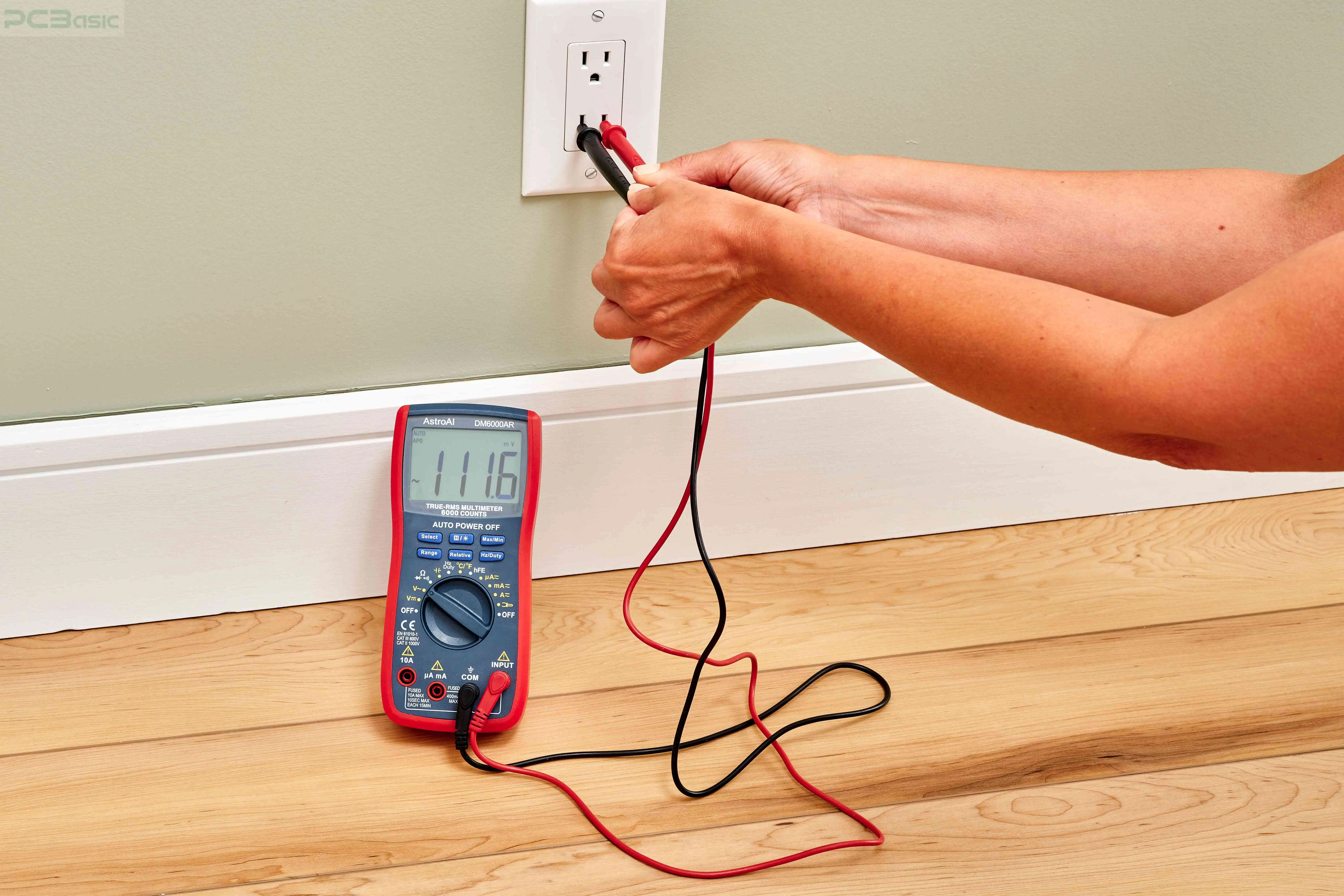
Here are just some of the other symbols you will see on a multimeter.
- COM: The black probe connects to the COM port, a common ground. It supports currents of up to 10A and guarantees reference stability throughout tests.
- A: Measuring up to 10A AC/DC currents in this terminal. One port is for testing higher currents, and to test, connect the red probe to this port. Make certain the fuse is good with a 600V CAT III rating.
- mAVΩ: An input jack handling volts, resistance and low currents, all in one. The ranges supported are 1mV to 600V, 0.1Ω to 40MΩ, 0.1mA to 200mA.
- mAµA: This input is intended for precise low current testing, down to microamp (µA) and milliamp (mA) ranges. They use it for their sensitive electronics and low-power circuits.
- VΩ: This jack measures the voltage and the resistance. It works safely up to 600V CAT III and 50MΩ resistances. Use insulated probes always for safety.
- Hz: The Hz symbol specializes in testing oscillators or timers measuring signal frequency in hertz. Professional model multimeters will support ranges up to 100khz.
- Shift: Secondary features accessible by the shift button include temperature measurement or non-contact voltage detection (NCV). To toggle hidden functions, press it.
- Hold: The hold button freezes the display reading so you can record or analyze data later. When readings move or the screen is unseen, it works.
 About PCBasic
Time is money in your projects – and PCBasic gets it. PCBasic is a PCB assembly company that delivers fast, flawless results every time. Our comprehensive PCB assembly services include expert engineering support at every step, ensuring top quality in every board. As a leading PCB assembly manufacturer, we provide a one-stop solution that streamlines your supply chain. Partner with our advanced PCB prototype factory for quick turnarounds and superior results you can trust.
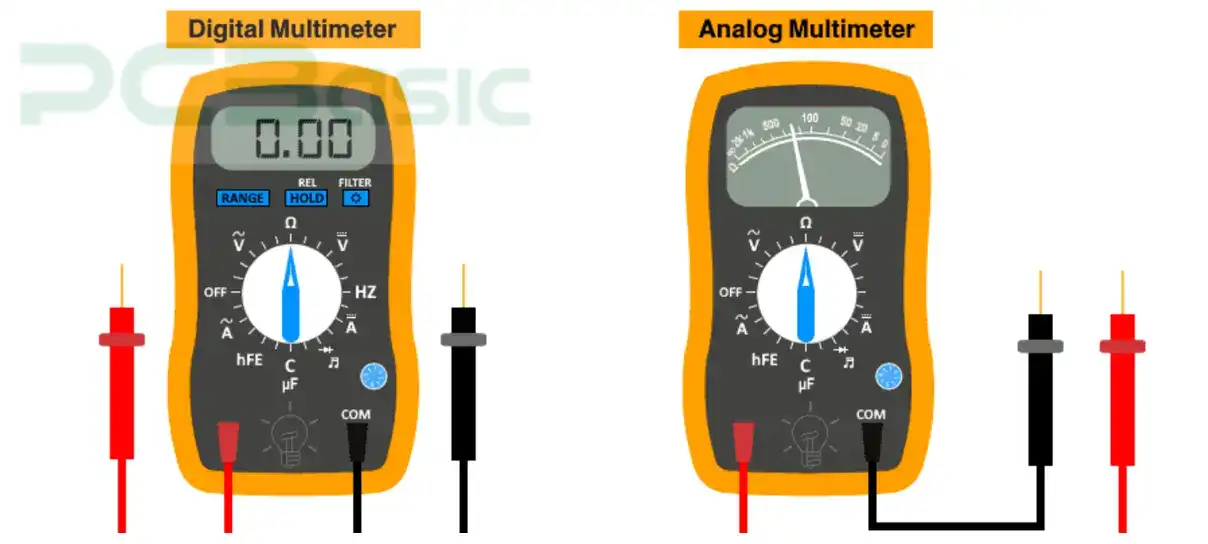
To measure volts (V), amps (A), and ohms (Ω), you use a digital multimeter (DMM). It has precision, but it displays values on an LCD screen. Current runs from 10µA to 10A and voltage ranges from 0.001V to 1000V. It ranges over 0.1Ω–50MΩ. These models often auto-range, switching to the right scale for you.
This is reliable, with accuracy levels of ±0.5%. You attach the probes to the COM and VΩA jacks. Understanding multimeter symbols helps you select settings. Tests use the capacitor symbol on this version for multimeter readings from 10nF to 10,000uF.
The needle pointer tells you to read measurements on an analogue multimeter. For AC/DC, it measures volts (V) from 0.1V to 1000V. Readings are from 10µA to 10A, and resistance checks from 1Ω to 10MΩ.
Analogue models don't have auto ranging, so you pick the scales yourself. Other accuracy is lower and is about ±2 – 3%, but it's very useful for checking trends of a signal. Setting up correctly will require the symbol for current, and the continuity symbol on the multimeter. COM and VΩ ports have probes connected. Unwired tasks and working without a battery for many functions, this suits durable tasks.
|
Feature |
Digital Multimeter (DMM) |
Analog Multimeter |
|
Display Type |
LCD Screen (4 digits, 2000 counts) |
Needle Pointer |
|
Voltage Measurement |
0.001V to 1000V (AC/DC) |
0.1V to 1000V (AC/DC) |
|
Current Range |
10µA to 10A |
10µA to 10A |
|
Resistance Range |
0.1Ω to 50MΩ |
1Ω to 10MΩ |
|
Auto-Ranging |
Supported in advanced models |
Not Available |
|
Accuracy |
±0.5% |
±2-3% |
|
Durability |
Sensitive to drops |
More durable in harsh conditions |
Table on Multimeter Types!
You define what you want to measure first. Adjust the dial to V~, V—, A~, A— or Ω. Use the right port: COM is black, VΩ or mA is red. If a 12V battery is used, set the DC voltage mode.
Attach probes safely to the terminals. You see the numbers on the LCD like 12.0V. Always know multimeter symbols: Equally like resistance would be given Ω or like continuity would be given sound. To remain secure, you must follow all required safety precaution.
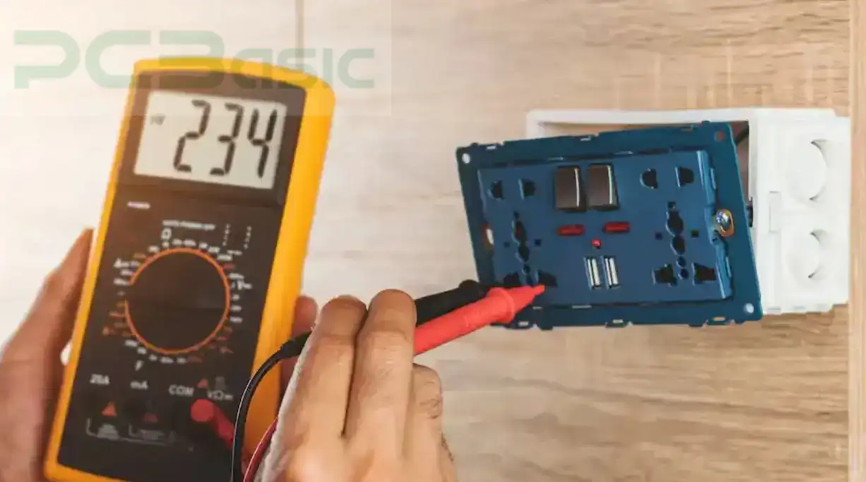
You read the screen number. Set the dial to V~, V—, or Ω. Use red in the right port. Select AC voltage for 230V mains and watch the screen. A range change if you can see OL.
For quick tests, use the continuity symbol. Hear a beep under 30 Ohm by connecting probes on the wires. Make sure you monitor readings of the multimeter correctly, and of course, protect yourself when working with a multimeter.
You always have to make sure to see if there’s any damage. Look out for cracks or worn-out leads. Make sure your test leads are CAT III 1000V safe to handle. Always measure under 750V AC or 1000V DC. Lead choices should include currents of 10A for maximum safety.
Familiarize yourself with multimeter symbols, like AC voltage symbol and resistance (Ω). You should use correct input ports like COM or VΩmA. Always set the higher range, say 20V DC, whenever testing for a 12V rail. Do NOT change modes on live circuits. Proper care of your meter is what ensures that it lasts. So, choose these steps for safer tests.
First decide on what measurements that you need. Find a meter capable of 1000V DC or 20MΩ resistance. You can prefer one with an accuracy close to ±0.5%. Learn what multimeter symbols mean to avoid errors. Go for a CAT III 600V meter safety.
Never go for overload protection like you get with 11A fuses. The meters auto-range easily between 200mV - 1000V DC. Choose extras such as backlit displays. We favor polycarbonate ABS for its durability. Advocate for those who need models up to 1000µF capacitance. Choosing these things makes your work safe and accurate.
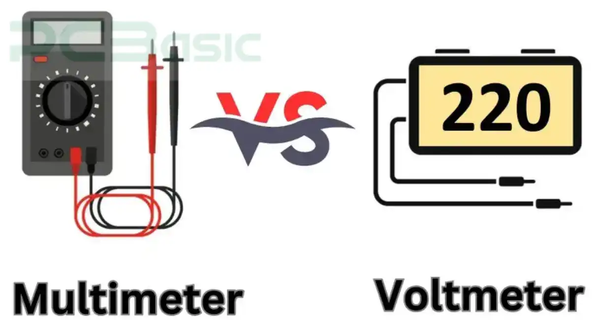
A voltmeter is used to measure voltage. Reaches up to 600VDC AC or 1000VDC. You connect it parallel to V+ and COM port. For accuracy it often has resistance at 10MΩ or higher. It can measure voltage, current (upto 10amp.) and resistance (upto 20Mohm). It even checks diodes, and continuity.
You must know multimeter symbols like 'V' and 'Ω' for proper use. Choose only after comparing their features. A voltmeter is about voltage. If you want additional features, then evaluate a multimeter. Choose the tool accordingly with your needs.
You measure current with an ammeter. It reads from 200mA to 10A. For the mA or 10A port, connect it in the series. This is below 0.1Ω to resist voltage drops. Voltmeter is used to measure the voltage; it usually measures up to 750V AC or 1000V DC. You connect it, in parallel across two points.
For precision it’s above 10MΩ resistance. Make sure to learn current symbol; voltmeter symbol. Before working, they should differentiate their uses. Choose your tool carefully by assessing circuits. Benchmark tools that will meet your exact needs.
You measure things with a multimeter. It will measure 1000V DC, 750V AC, or 20MΩ resistance. You attach probes to VΩmA and the COM port. You must know multimeter symbols like 'A' and 'V' for accuracy. A current can be measured without contact using a clamp meter.
Jaws that can detect magnetic fields around wires. When used to read AC and DC current, clamp meters can read up to 1000A safely. These tools are quite different. Multimeters are versatile. Current testing is all that clamp meters care about. It helps you decide on your tool because of the contrast. Pick what fits your circuit.
You understand multimeter symbols and their uses. Now you can measure circuits safely and correctly. Learn about each piece and what it does. Looking for more tools? Check out PCBasic!

Assembly Enquiry
Instant Quote
Phone contact

+86-755-27218592
In addition, we've prepared a Help Center. We recommend checking it before reaching out, as your question and its answer may already be clearly explained there.
Wechat Support

In addition, we've prepared a Help Center. We recommend checking it before reaching out, as your question and its answer may already be clearly explained there.
WhatsApp Support

In addition, we've prepared a Help Center. We recommend checking it before reaching out, as your question and its answer may already be clearly explained there.
