Global high-mix volume high-speed PCBA manufacturer
9:00 -18:00, Mon. - Fri. (GMT+8)
9:00 -12:00, Sat. (GMT+8)
(Except Chinese public holidays)
Global high-mix volume high-speed PCBA manufacturer
9:00 -18:00, Mon. - Fri. (GMT+8)
9:00 -12:00, Sat. (GMT+8)
(Except Chinese public holidays)
HomePage > Blog > Knowledge Base > IPC-2221 | PCB Design

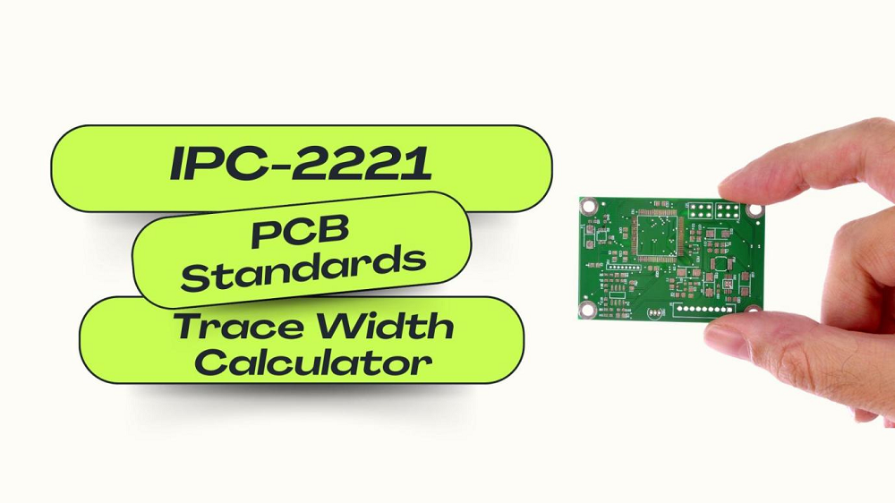
The design of a printed circuit board entails standards for many aspects of a PCB, from inputs to outputs, to produce quality, reliable, and safe products. One of the foundational standards is IPC-2221 because it was instituted by the Association of Connecting Electronics Industries (IPC) as the universal standard for designing PCBs and other forms of interconnecting structures. This standard provides crucial guidelines in all other aspects relating to PCB design, from the selection of material up to trace width and spacing requirements, which are critical factors to the performance and the durability of the board.
IPC 2221, therefore, ensures uniform expectation levels for PCB vendors so that the products produced are of quality and reliability and are safe, for example, in applications where failure of a PCB can never be allowed as their applications are in aerospace and medical technology fields and automotive. Manufacture benefits from the standard IPC 2221: product integrity is strengthened, and customer confidence in final product quality and reliability is increased. IPC-2221 becomes the general standard upon which much of the PCB design process is based and is essentially fundamental to anyone working to uphold best practices.
IPC 2221 is the internationally recognized worldwide standard developed by the Association of Connecting Electronics Industries or IPC, giving comprehensive PCB and other electronic assembly design guidelines. It was published in the year 1998, and updates are continually due and scheduled, operating on all aspects of PCB design, including material choice, trace width, trace spacing, and component mounting. The generic standard is considered to be IPC-2221 because it was developed as a basis for further specialized PCBs that are aimed at ensuring that all circuit boards meet a minimum design and safety profile, regardless of specific application needs.
In the history of development, IPC-2221 sprang to life because of the continually increasing demand for consistent PCB manufacturing in industries as they ushered into faster electronics and circuit board design complexity. Mostly, it was created to set uniform requirements that would help manufacturers produce safe, high-quality PCBs that could reliably function in areas such as consumer electronics, telecommunications, and aerospace.
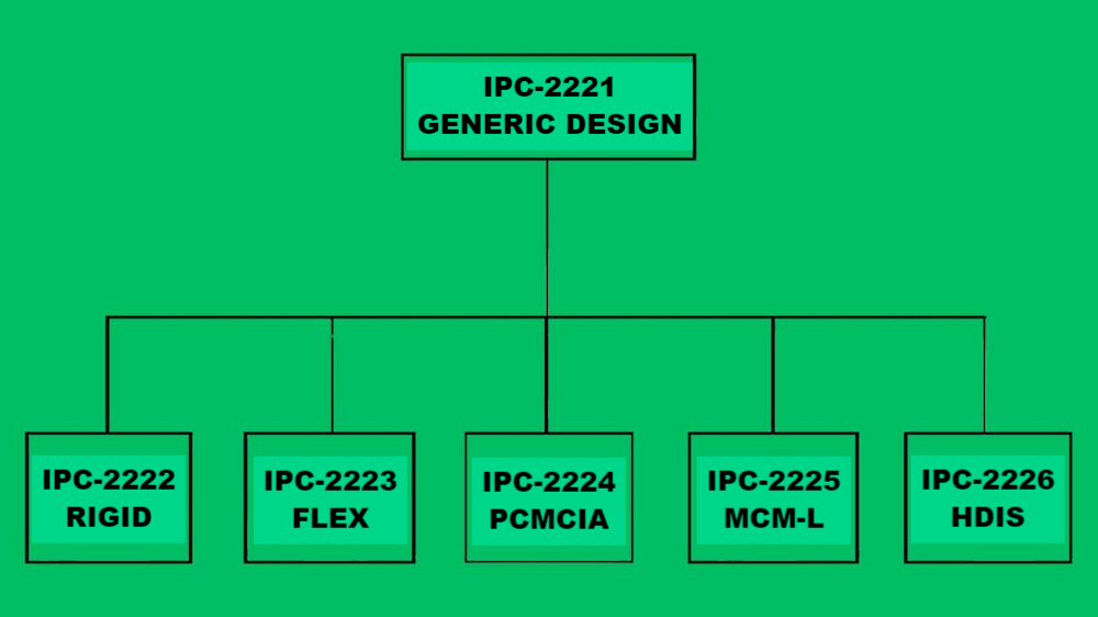
No exaggeration is in order because IPC-2221 forms a basis for all classes of the IPC standards. Rigid PCBs fall under the umbrella of IPC-2222, Flexible PCBs fall under the umbrella of IPC-2223, and specifics fall under the application of the PCB. In other words, IPC-2221 provides design engineers with a universal guide that gives consistency from project to project and line of products to line of products. This signifies that the designs are safe and reliable enough to accept the desired electrical loads. Trace width, trace thickness, component spacing, and material characteristics are determined by IPC-2221's electrical and thermal requirements.
The requirements set forth by IPC-2221 are not only applicable to single designs. Uniformity in the application of these designers and manufacturers will also bring predictable quality to industries. This would also make cooperation easier in product integration since designers, manufacturers, and end-users can all comfortably understand the board specifications they apply.
Maintaining reliability and market trust through products is very important for a company. Adherence to the requirements of IPC-2221 would be quite significant for a good design of PCBs, considering electrical performance, endurance, and safety. These may become crucial in high-risk-type industries where failure in PCB will cost or even be detrimental to health and other operational safety considerations. This set of standards by IPC also adds a reputation to the company in the market.
Customers and business partners trust companies that have guidelines from IPC since they reflect the seriousness of companies' commitment to quality and best practices. The design and manufacturing of PCBs directly affect the end product, and technical know-how and credibility are reflected through the compliance of IPC-2221. That repeats the status of the manufacturer. More opportunities for business beyond this.

IPC standards are hierarchical in satisfying the varied demands and the ever-rising complexities of PCB design. This hierarchy enables each of the standards within the family of IPC to settle on specific subjects of board types since it covers specific design considerations starting from the application, material composition, and structural characteristics that the board is intended for. The IPC classifies standards. Hence, it allows design engineers to refer to the most applicable standards to a project that might be rigid, flexible, multi-layered, or high-density boards. It standardizes the approach used in PCB design by meeting specific standards and requirements without causing overlaps or ambiguities.
It finds its establishment from general or base IPC-2221 as this hierarchical structure, and special or specific guidelines for particular materials, structures, board characteristics, or whatnot branch further from there to give the designer targeted but relevant guidance within broad design principles. This would give much-needed support in the direction toward consistency and coherence in design practices related to different kinds of boards and, hence, will end up supporting quality and reliability in the final product.
Below is the summary of the major categories under the IPC-2221 hierarchy with their respective descriptions:
|
IPC Standard |
Description |
|
IPC-2222 |
Board rigidity standards This describes the layout requirements for hard and strong rigid boards. |
|
IPC-2223 |
Design considerations for flexible printed boards are guidelines by which the use of materials that will bend or flex must be considered. |
|
IPC-2224 |
High performance multilayered printed boards standards. This design document is on multilayer PCB design criteria with a focus on space saving through complex circuitry. |
|
IPC-2225 |
The IPC-2225 establishes organic printed boards with conductor layers through bonding layers and material properties. |
|
IPC-2226 |
HDI Boards Guidelines This standard covers the design of high-density boards with closely packed components and fine-pitch characteristics, mainly used in compact or high-speed electronics. |
All of these requirements, based on the general principles provided by IPC-2221, allow manufacturers and designers to design boards according to specific performance and application needs and yet allow a uniform approach to quality and reliability across the PCB industry.
The standard IPC-2221 is considered to be an all-inclusive guide to PCB design including choice of materials, layout, and electrical requirements so that performance and reliability are assured. This section will highlight a number of key issues in this standard including material selection, design dimensions, and considerations for high-power applications.
This is one of the important decisions in PCB design as it makes several electrical and mechanical performances of the board, and one of the general documents on this is IPC-2221, which gives information on some common PCB materials, such as FR-4 fiberglass-reinforced epoxy laminate for standard applications and high-performance materials like polyimide for flexible or high temperature requirements. Material selection should further be guided by dielectric properties, moisture resistance, and thermal conductivity because these properties affect signal integrity, thermal management, and overall durability.
emphasizes standardization to achieve compatibility and functionality. Board dimensions should be planned in a way that no amount of stress is seen upon assembly; size restrictions should meet special requirements of a particular device. The panelization practice is also recommended in the standard, which refers to how more boards are allocated in one single manufacturing panel for the efficient production of material saving practices.
Components mounted on a PCB must be designed such that functionality is ensured and EMI or thermal hotspots avoided. IPC-2221 is a guide for spacings, orientations, and locations of components to provide optimal assembly efficiency while maintaining performance. For instance, in the design, power transistors are components that generate heat. They need to be placed in a way that will ensure maximum airflow and cooling. Analog components that are sensitive ought to be located away from high-speed digital circuits to reduce interference effectively.
Trace and space guidelines are amongst the most crucial guidelines in IPC-2221. Trace width and trace spacing between traces, according to the guideline, should be followed so that designs are safe and efficient. To calculate the best trace width of each trace to be undertaken, depending on current, temperature rise limit, and numerous more factors, etc, IPC trace width calculators are widely used in computing. Maintain trace width appropriate so no overheating and potential shorts are formed. Adequate spacing allows traces not to interfere electrically with one another.
In high-voltage applications, clearance and creepage are critical to safety. Clearance is the distance between two conducting parts measured through air as the shortest distance possible. Creepage is the distance over the surface of an insulator. IPC-2221 specifies specific distances for clearance and creepage, in a manner that must prevent arcing and, in turn, electrical breakdowns from occurring, thus leading to failure within a PCB.
IPC 2221B defines by voltage level the clearances that designers can use to select appropriate clearances for any application. For example, higher voltages require increased clearances; however, applications like power supplies and medical products require clearances of higher voltages, as safety is paramount. Therefore, considering these standards ensures that designs adhere to regulatory safety standards as well as performance.
High-powered products, from motor controls to power converters, have special requirements because they can carry higher currents. IPC-2221 has trace width and thickness recommendations that may be altered to prevent overheating. Thus, the most recent version of the standard IPC-2221B refines the application of high-powered elements absolutely required by a power-consuming design engineer.

Although vias are very critical to connections between the PCB layers, via sizing, plating, and spacing may be recommended under IPC-2221. Properly designed vias prevent thermal stress and mechanical failure once the circuit starts working. One will use a via current calculator in choosing an appropriate via size for any desired current, especially in high-current applications.
The traces of the PCB should be thick enough to carry out the current without overheating. Trace thickness according to IPC-2221 is dependent on the amount of current each trace carries, and this would ensure stability and dependability during the lifetime of the board. Trace thickness is very critical at high currents because excessive overheating would melt the traces.
Thermal management will also play an important role in PCB design. High temperatures can degrade some of the components and reduce their life. Ipc-2221 provides guidelines for thermal via, heat sink, and trace layout for a PCB to dissipate heat, especially for high-power-density designs.
The metal migration phenomenon can be known as the diffusion of metal ions between traces. Sometimes, it leads to short circuits. Specifying a minimum trace spacing and using protective coatings can eliminate it from IPC-2221. Increasing the reliability of PCBs could meet these recommendations; this reduces the failure rate - especially when working under high humidity and a high voltage.
While IPC-2221 remains the general guide to PCB design, in most applications it is used in combination with other IPC standards. These all relate to specific areas of the PCB manufacturing and performance requirements. The following is a comparison of IPC-2221 with some related standards.
|
Standard |
Description |
|
IPC-2221 |
General standard for PCB design, incorporating all materials, layouts, and electrical consideration. |
|
IPC-9592B
|
Sets requirements for power conversion devices (PCDs), such as power supplies used in computing and telecommunications, focusing on reliability, safety, and durability. |
|
IPC-2581
|
A standard data transfer format for PCB design and manufacturing, enabling seamless transfer of design data and specifications from design tools to manufacturing. |
Such a hierarchy would enable designers to follow complete guidelines for generic as well as specific requirements so that quality in the PCB from various applications may be uniform.

Trace Width, through the equations presented by IPC-2221, thereby provides for safety with minimum overheating across all parameters of operation. Its conventional method is based upon parameters of current load, and ambient temperature, as well as the rise in temperature. Although an IPC standard, a commonly used formula is:
Trace Width = Current / (k × (Temp Rise)^(1/b))
The obtained constants k and b come from the standard IPC and may vary between traces internal and external. One can obtain such trace design by computing as feasible that is both secure as well as strong.
Vias are very essential for inter-layer connections, and thus their calculation should also be accurate for current-carrying capacity so that it would not reveal the possibilities of failure. In terms of the diameter of vias, copper thickness, and number of parallel vias, the current calculator application allows safe current distribution via its mentioned inputs. Thus, the inputs provide designers an opportunity to surpass thermal stress or even avoid thermal breakdown when subjected to load.
Trace current calculators give the maximum amount of current a trace can carry in designs for high currents. This depends mainly on the trace width and thickness and ambient temperatures. The traces will ensure not to take more than their limit so as not to cause overheating. This is very crucial for applications that include power-intensive components.
IPC-2221 outlines standards for PCB design consistency and reliability between industries. Design engineers can provide reliable PCBs by strictly adhering to all of the standards stipulated under IPC-2221 and other associated standards in order to meet the industrial specifications and customer needs. Such compliance therefore offers durability for the products, which in turn enhances the quality of manufacture, a factor that directs market competition and sustainability.

Assembly Enquiry
Instant Quote
Phone contact

+86-755-27218592
In addition, we've prepared a Help Center. We recommend checking it before reaching out, as your question and its answer may already be clearly explained there.
Wechat Support

In addition, we've prepared a Help Center. We recommend checking it before reaching out, as your question and its answer may already be clearly explained there.
WhatsApp Support

In addition, we've prepared a Help Center. We recommend checking it before reaching out, as your question and its answer may already be clearly explained there.
