Global high-mix volume high-speed PCBA manufacturer
9:00 -18:00, Mon. - Fri. (GMT+8)
9:00 -12:00, Sat. (GMT+8)
(Except Chinese public holidays)
Global high-mix volume high-speed PCBA manufacturer
9:00 -18:00, Mon. - Fri. (GMT+8)
9:00 -12:00, Sat. (GMT+8)
(Except Chinese public holidays)
HomePage > Blog > Knowledge Base > What is Flying Probe Testing?
In the printed circuit board (PCB) manufacturing process, testing is a crucial stage to ensure product quality. At present, common PCB testing methods include In-Circuit Testing (ICT), Flying probe testing (FPT) and 4-wire Kelvin Testing. Flying probe testing is a popular method among them, using specialized flying probe testers to test printed circuit boards, circuit board components, individual components and the whole circuit board system. It is widely used in small batch production and prototype production because of its unique advantages.
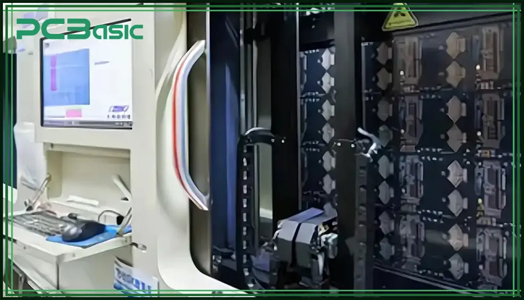
Flying probe testing is an automated electronic circuit test method, mainly used to check the electrical performance of the circuit board or components on it. The flying probe testing is operated by the test program to flexibly and accurately control the position and movement of multiple probes, so that they can quickly and accurately move between various test points to test a single circuit board or an entire circuit system.
Compared with traditional bed-of-nails test, flying probe testing is highly flexibly. Because flying probe testing does not require test fixtures, the test program can be easily adjusted according to different board designs to adapt to diverse and rapidly changing actual environments
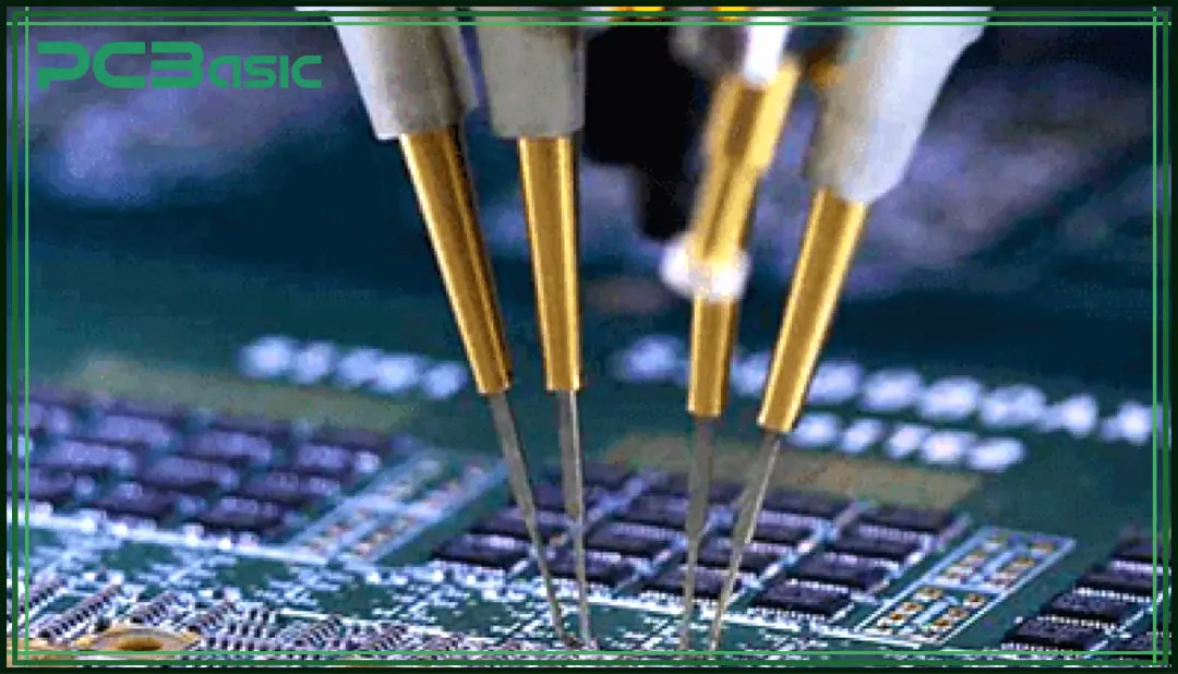
A complete flying probe system is composed of a series of components, including probes, robotic arms, control system, test station, camera system, electrical measurement equipment, user interface, software, safety features and calibration tools, user interface, software, safety features and calibration tools. Among them, the most important are these three parts:
Probes: Probes are the core part of flying probe testing. These are not just simple points of contact; they are precision instruments designed to connect with specific locations on the PCB to measure electrical properties like resistance and capacitance. The accuracy and condition of these probes are crucial, as they directly affect the reliability and precision of the test results.
Test station: It provides a stable platform for tested circuit board and usually contains adaptive fixtures that can be adapted to various sizes and shapes of the PCB.
Control software: This is crucial for managing the complex data and operations of a flying probe tester. It not only controls the machine's movements and test sequences but also handles data processing, result logging, and often predictive diagnostics, which can foresee potential PCB failures before they occur.
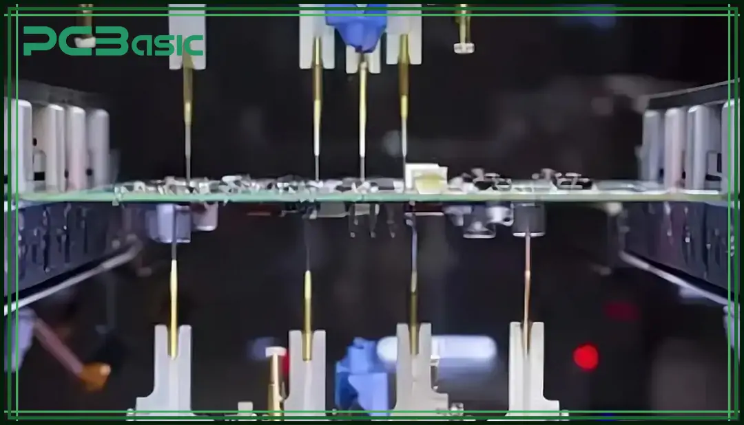
As a quality control tool in circuit board production, flying probe testing is popular among manufacturers because of its highly flexible and changeable characteristics. There are five main types of flying probe testing systems.
Single-sided flying probe testing systems are equipped with probes that intelligently inspect one side of the board at a time, often used to test single-sided boards or simpler board designs that have fewer inspection points. Single-sided test systems can also be used to check single-sided PCBs for electrical problems such as soldering connectivity, short circuits, open circuits, and wiring problems.
At the same time, as the single-side test system is relatively simple, so the cost is low and the operation and maintenance is also relatively easy, it is very suitable for quick turn PCB and PCBA.
Double-sided flying probe testing system refers to the tester is equipped with probes on both sides of the board, which can test both sides of the PCB at the same time. This system is suitable for more difficult circuit boards with high component density, or more complex structure, as well as multiple-layer PCBs. At the same time, compared with the single-sided, the double-sided test system can test faster and more accurately, which is suitable for large-scale PCB production.
Of course, the cost is also relatively high.
The high-speed flying probe testing system is unique in its outstanding test speed. Because the advanced motion control technology, high precision probe and optimized control software, the system can greatly improve the overall speed of the test on the premise of ensuring the testing accuracy. Therefore, this type of system has a huge advantage in high volume production and when production schedules are tight.
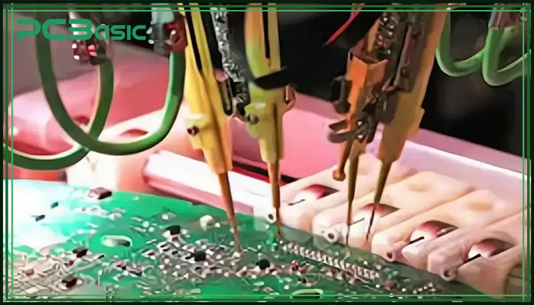
Flying probe testinging is a complex process, and every step needs to be carefully checked and carefully operated.
Before the test begins, the operator needs to create a test program in the system to configure the specific design details of the PCB, including inputting layout data, circuit diagrams and test points into the system's software.
The core of the flying probe system consists of several robotic arms, each equipped with one or more precise probes. These probes can move independently across the surface of the PCB. The movement is controlled by sophisticated software that directs the probes to touch specific test points on the board, based on the pre-loaded design information.
Once the probes make contact with the PCB, they can perform a variety of electrical tests. Common tests include continuity tests to check for open circuits, isolation tests to ensure there are no unintended electrical paths between unconnected nets, resistance, capacitance, and inductance measurements to verify component values, as well as functional tests to simulate the operation of circuit components and check for correct operation.
As the probes contact the test points, they send data back to the control system. This data includes measurements of electrical properties and any detected faults. The system’s software analyzes this data in real-time to determine if the PCB meets the specified electrical requirements.
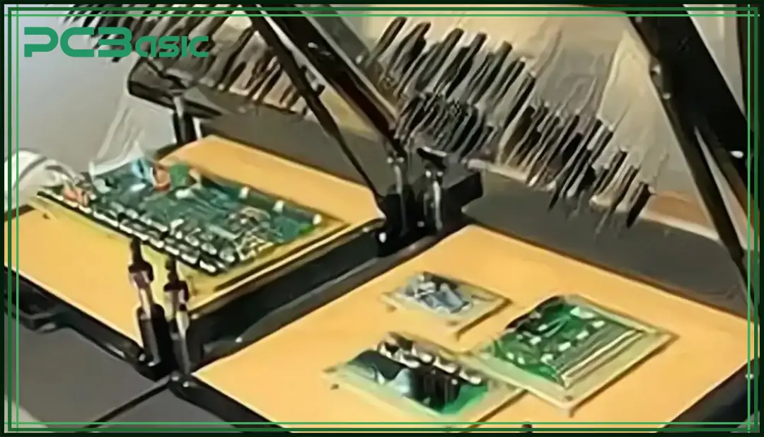
In-circuit testing (ICT) is also used to verify the components on a printed circuit board are and their functionality. It is carried out using a bed-of-nails tester, where spring pins are pressed to specific test points on the PCB to measure electrical characteristics such as resistance, capacitance and voltage, as well as perform functional checks. In-circuit testing can quickly identify manufacturing defects such as incorrect component placement, soldering errors, and component failures. While ICT requires a significant initial investment in custom fixtures and lacks flexibility for different PCB designs, its high fault coverage and accuracy make it ideal for high-volume production environments where reliability is critical.
While both ICT and FPT serve the purpose of PCB testing, they differ significantly in approach and application:
|
Aspect |
In-Circuit Test (ICT) |
Flying Probe Testing (FPT) |
|
Fixture Requirement |
Requires custom fixture (bed of nails) |
No fixture required |
|
Cost |
High initial cost for fixtures |
Lower initial cost |
|
Flexibility |
Limited, fixtures need redesigning for changes |
Highly flexible, programmable |
|
Best Suited For |
High-volume production |
Low to medium volume, prototypes |
|
Testing Speed |
Faster for high volumes |
Slower for high volumes |
We can clearly see the importance of FPT in ensuring the quality control of electronic manufacturing. As technology continues to evolve, flying probe testing has become a key step in ensuring that boards meet high performance standards during production.
In the future, as electronic products become more and more miniaturized and highly functional, flying needle testing technology will also be further innovated to adapt to more complex circuit board designs and more stringent testing needs. For manufacturers, investing in advanced test technologies and continuous improvement of test processes will be key to increasing competitiveness, reducing risk and winning the market.

Assembly Enquiry
Instant Quote
Phone contact

+86-755-27218592
In addition, we've prepared a Help Center. We recommend checking it before reaching out, as your question and its answer may already be clearly explained there.
Wechat Support

In addition, we've prepared a Help Center. We recommend checking it before reaching out, as your question and its answer may already be clearly explained there.
WhatsApp Support

In addition, we've prepared a Help Center. We recommend checking it before reaching out, as your question and its answer may already be clearly explained there.
