Global high-mix volume high-speed PCBA manufacturer
9:00 -18:00, Mon. - Fri. (GMT+8)
9:00 -12:00, Sat. (GMT+8)
(Except Chinese public holidays)
Global high-mix volume high-speed PCBA manufacturer
9:00 -18:00, Mon. - Fri. (GMT+8)
9:00 -12:00, Sat. (GMT+8)
(Except Chinese public holidays)
HomePage > Blog > Knowledge Base > Understanding Electrical Schematics: A Comprehensive Guide
Are you a seasoned designer or new to the electrical field? If yes, then you must start from the basics. You must be wondering what an electrical schematic is in the first place. Then, worry not. I’ll be walking you through the concept.
To start with, schematic symbols or electrical schematics are comparable to the language of circuits. Why are they important? Because it helps you comprehend the objective of your circuit design. Reading and understanding it is not a technique you should learn and forget, but it is a necessity. Now, when you're aware of the importance of an electrical schematic but not sure how to read it, this article is for you! So, let's not waste any of your time and dive into the details of electrical schematic components, ways of interpreting them, and more.
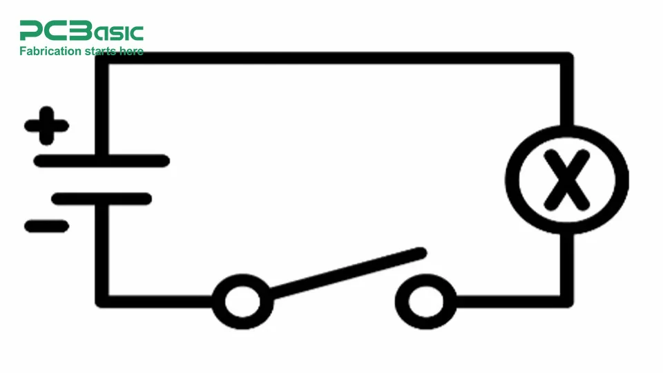
An electrical schematic is another method to display or draw out the electrical route of your circuit. The term electrical schematic is a technical illustration used for an individual to think about the basic components and their association in an electrical circuit. Circuit layouts of traditional design show only the physical arrangement of the system and working hours whereas an electrical schematic tells you how electricity moves and connects in the system.
Let’s now take a look at key features of electrical schematic symbols, including:
● Variable resistors, push-button switches and diodes.
● It encompasses not only the location of the circuit components, but the order of these concepts.
● It is also a means of communication understandable across the world of engineering.
● Offers specific information as to whether the component is an original, its worth, or its rating.
In short, without schematics, there would be a total mess to find faults, create circuits, and build systems.
Here’s a list of the common elements typically found in an electric schematic, along with an explanation of their meanings:
● Lamp: It is represented as a circle with a cross in it. It looks more like a light bulb or lamp where a light turns on when current is introduced through it.
● Switch: It shows up as a break in a line with an angled line between the two ends. It regulates the flow of current in a circuit.
● Wire: This straight line shows the connection between the components in the circuit.
● Connected/Not Connected: Such wire symbols specify whether wires are connected (thin line with a point) or not (crossing of dotted lines without a point).
● Resistor: It is shown as a zigzag line that restricts electrical current while permitting different parts and circuit practices.
● Variable Resistor: It is a resistor with an arrow through it, which indicates it’s a resistor where you can adjust its resistance to control current.
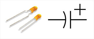
● Capacitor: It holds electrical energy and gives it as required, often to 'smooth’ or 'filter’ signals.
● Polarized Capacitor: Basically, a polarization capacitor is any regular capacitor but one that has the polarity marked by (+) and (-). It is used in DC circuits.
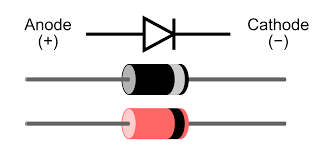
● Diode: It features a triangle arrow that points to a line, and that only lets current run in one direction, to protect sensitive components.
● LED (Light-Emitting Diode): Where there is an LED or light-emitting diode, we have the arrows that point outside where there is one directional current.
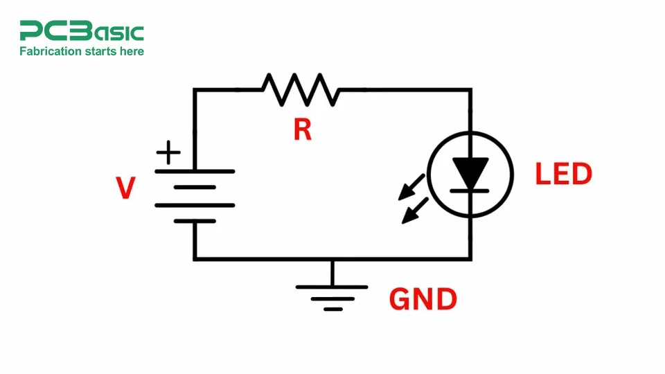
When learning to understand the basics of a circuit, you should have the key components on your sleeves. First of all, what is a circuit? In other words, a circuit is something that any electrical current flows through. Easy, right? Well, let’s get in a bit more and look at the main parts to think about in building your own circuit configuration.
Here’s how a circuit works:
When a power source pushes electrons through conductors in a closed path, these electrons flow around in a circuit to produce current.
For current to flow:
● The circuit path should not have broken, it must be closed.
● The power source’s positive terminal must force the current through the circuit and back out onto its negative terminal.
No, we all know how a circuit works, so let’s move onto the different kinds of circuits we would likely encounter.
● Series Circuit: In this, the current goes through the components one after another in a single path. If one component of the circuit fails, that affects the entire circuit.
● Parallel Circuit: This circuit represents components set up in various branches, where only one route for current to flow is permitted. If one part goes bad, everything else still works fine.
● Combination Circuit: It consists of series and parallel configurations to meet some design goals.
So, let’s look at the basic laws circuits do have.
It explains the relationship between voltage (V), current (I), and resistance (R). It is important to understand how voltage, current, and resistance in a circuit behave.
V= I×RV = I \times
RV=I×R
Kirchhoff's Current Law (KCL) states that:
The sum of the total current entering an electrical circuit junction is the same as the total current leaving the junction. The formula for KCL is:
∑I(in) = ∑I(out)
Where:
I(in) is the currents flowing into the junction.
I(out) is the currents flowing out of the junction.
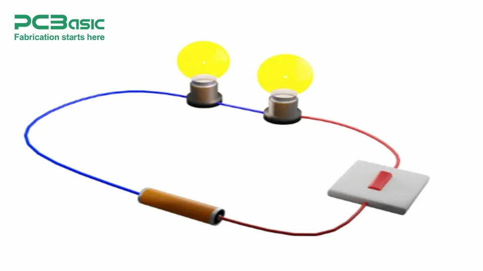
When it comes to representing a circuit, what is it? Is it some diagram filled with SI units? Or a diagram of a flow chart type? I’ll be for real with you, I don’t believe it is one-size-fits-all. There are several graphical representation methods in the market, each one having its benefits. Which one of these pieces fits best for your next use in the project? Let’s break it down for you. By the end of this section, you'll know which of the graphical designs you should choose.
They are blueprints for your circuits. What do they have to offer? They are basic to represent so that a novice can understand. They are meant to bridge the communications between the components. Rather than looking at the physical design of the circuit, they use wiring diagram symbols to see the circuit’s use.
After that, we have a wiring diagram on the page. It gives a more practical view of integrated circuits. It's not the boring old-school abstract symbols that are being shown to you; it's how easily your component plays in the real world. This one lets you install and repair the color of your wires, your physical connections, and the placement of your terminals.
What impression does this graphical representation create in your mind when you come across the term "block diagram"? Is it a flowchart or blocks? If you're going with the flowchart, you could well be right then. This flowchart-type diagram gives a bird's-eye overview of the system. It breaks the diagram into two sections:
● Power Supply
● Operational Amplifier
The best part of it? It doesn’t go on to the nitty gritty. But it analyzes how that piece of content fits into the hole it fills. When you know you are going to build a block diagram for the next project, pay attention to this one, as it has a good side for high-level planning or explaining the systems to nontechnical folks.
This one is hands-down our favorite because it's the friendliest format for beginners and non-experts. Who doesn't like a visual? I mean, we all do. The easiest and most surefire way of memorizing a circuit is to see its picture instead of reading all the symbols. Overall, it replaces symbols with realistic illustrations, so it is easier to see how the circuit reacts with its counterparts.
Whereas, sometimes a single-line diagram can become complex. But if you've finished with them, they can break down your complex electrical systems into clean, sleek, single-line representations. Nevertheless, it focuses on the large parts of the power lines, the transformers as well as the circuit breakers, and because of this, it is more ideal for the bigger system including the industrial power grid and electrical building layouts.
All engineers, electricians, and hobbyists should be able to read a circuit diagram. A circuit diagram (also known as a schematic) is a symbolic representation of the portions in an electrical system. Here’s how you can read them.
The trick here is that you need to understand the components first. For example, in circuit diagrams, components are represented by standardized symbols. But which symbols? Here’s what they are:
● Resistors: Represented as lines or zigzag.

● Capacitors: Parallel lines (one straight, one curved for polarized capacitors).
● Diodes: Triangle points in a line, making the direction of current flow.
● Power Sources: Long and short lines for batteries, or wavy lines for the case of AC source.
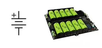
With the symbols already known, you're ready to see how the circuit is powered. But how do you do that? Firstly, you should find out the power supply: it is usually a battery or an AC power plug. After that, record its polarity or voltage rating. For instance, if it is a DC circuit, a longer line stands for the positive terminal and a shorter line for the negative.
It’s time to check where your circuit current is going and if its flowing in the right or wrong direction. Normally, electric current runs out of the power’s positive terminal and into its negative terminal. This is shown to be more susceptible to the conventional current flow. To read that, just trace the path from the power source through the components and back to the source, and you’ll know your current flow path.
Once all of those steps are done, you have to analyze all separate connections. At the start, it might seem a bit difficult, but it really does go a long way. The only thing you need to know is what each component does. Let me break it for you.
● Resistors: Limit current flow. Note the values of the resistance (in ohms) printed beside the symbol.
● Capacitors: They also store and release electrical energy. We should look for capacitance values in farads.
● Switches: Control the flow of current. Open switches break the circuit; closed switches close the circuit.
● Diodes: The diodes allow the flow of current in only one direction. Then you look for the anode (positive) and cathode (negative) terminals.
● LEDs: They emit light like diodes for current. You have to notice the polarity of their signals.
Finally, here’s the easiest part. You've got to know whether it's a series configuration or a parallel configuration of the electrical schematic. If they’re attached end to end, they’re a series. The other case where the components are connected across the common two points is called a parallel circuit.
If you’re a hobbyist looking to build some simple gadgets, it is almost essential that you learn how to read and interpret a schematic diagram. Reading a schematic is like learning to read a map: If you know what it all means, you can find your way. For example, a particular symbol is used for each component: a zigzag for resistors, parallel lines for capacitors, and triangles for diodes. You have to know them well at first to understand a schematic diagram.
You’ll want to get to know these symbols, their function, and what they look like. You’ll then have to find the power source. It will be labeled a+++ or battery symbol and you'll then trace along the lines (wires) to the components to look at the flow of current.
Then you go looking for labels like R1R1R1 or C1C1C1, letting you know about resistance components in ohms or, for capacitors, components in farads. Once you know the function of each part of the circuit, try to trace the route that electricity travels. This way, you would easily understand and interpret a schematic diagram.
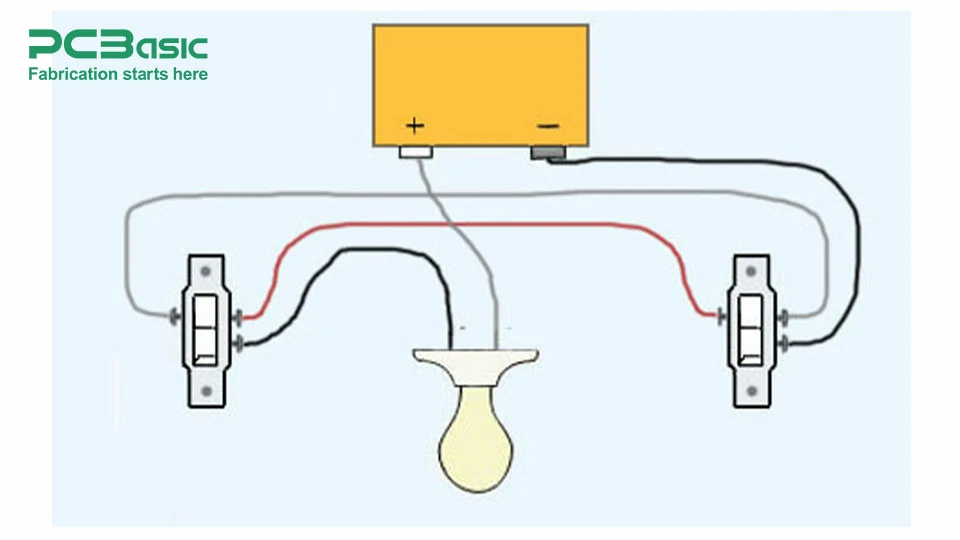
Many people do not realize the simple steps involved when they wish to design a schematic diagram. Making a professional-looking schematic diagram is not simple. But once you know the right steps, you’re on your own with the next high tech wiring diagram. If you are starting out, using schematic design software like KiCad, Eagle, Altium, etc will work. Then arrange the selected circuit of systems into functional blocks (Input, Process and Output), flowing left to right or top to bottom to indicate signal or power progression.
After this, you basically need to use the normal electrical symbols so that everyone will understand. All components must be assigned unique identifiers (e.g., R1, C2, U3, etc) and all values (resistance, capacitance, if applicable IC part number) must be noted. Adhering to these is the only way to be sure your schematic will work, look good, and make sense.
Schematic diagrams are a blueprint for assembly, troubleshooting, and collaboration. It professionally communicates a circuit’s functionality and structure. After following industry standards, organizing components in a rational manner, and highlighting the clarity, they make sure that your diagrams are not only useful but also sweet to the eyes.

Assembly Enquiry
Instant Quote
Phone contact

+86-755-27218592
In addition, we've prepared a Help Center. We recommend checking it before reaching out, as your question and its answer may already be clearly explained there.
Wechat Support

In addition, we've prepared a Help Center. We recommend checking it before reaching out, as your question and its answer may already be clearly explained there.
WhatsApp Support

In addition, we've prepared a Help Center. We recommend checking it before reaching out, as your question and its answer may already be clearly explained there.
