Signal and power integrity are the best indicators of a suitable electronic product. Achieving a high level of integrity starts with understanding critical electronic components. Therefore, a good electronic designer and engineer should have exemplary knowledge of electronic component selection, specification, and each component's role in the circuit.
One such electronic component is a capacitor. Capacitors, such as AC filtering, play critical roles and exist in various types. This article focuses on decoupling capacitors, what they are, how they are compared with coupling and bypass capacitors, how to select and where to place them, and finally, where they are used.
What is a Decoupling Capacitor?
Fundamentals of Decoupling Capacitors
A decoupling capacitor is a passive electronic component that filters DC voltages and smoothens their flow in an electronic circuit. It is used as a voltage bank, ensuring power fluctuations do not occur when circuit demand rises. The capacitors are always placed near the power inputs of electronic devices such as MCUs.
· Decoupling capacitors store energy released immediately after the circuit requires it, thus ensuring steady flow.
· They operate like a short circuit, protecting sensitive components.
· Every designer and engineer should be able to choose the right decoupling capacitor to guarantee better noise reduction.
· Before selecting the capacitor, check its ESL, ESR, and capacitance for optimal performance.
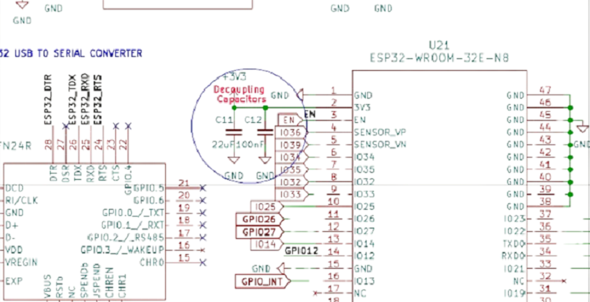
Figure 1: Decoupling Capacitors in ESP32_WROOM_32E_N8 Development Board Main Input Power
Coupling vs. Decoupling Capacitors
Coupling capacitors are used in signal lines, unlike decoupling, which is used between power lines. In other words, decoupling capacitors are connected in parallel with the power signals to filter out AC signals. In contrast, coupling capacitors are connected in series with the power signals to filter out DC signals. Both coupling and decoupling capacitors are found in both digital and analog circuits.
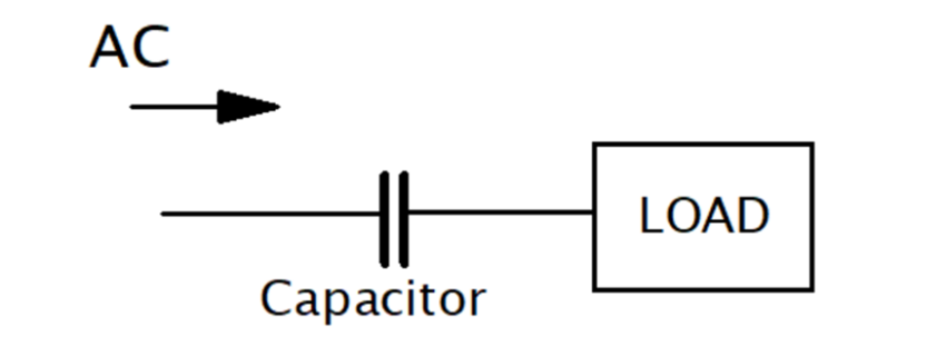
Figure 2: Coupling the Capacitor in Series with the Circuit Signals
Below is an exhaustive difference between coupling and decoupling capacitors:
Table 1: Table of Differences Between Coupling and Decoupling Components
|
Specification
|
Coupling Capacitor
|
Decoupling Capacitor
|
|
Function
|
Used in transferring AC signals and disallowing DC ones
|
Used in Voltage stabilization and noise filtering
|
|
Placement
|
Placed between circuits signal lines
|
This is placed between the circuit power supply and the electric load, close to the load power input.
|
|
Application
|
Rf circuits, Audio signals
|
MCUs, ICs, digital systems
|
Decoupling vs. Bypass Capacitors
Unlike decoupling capacitors, bypass capacitors are used in electronic circuits to “bypass” unwanted noise interference by creating a low-impedance path to the circuit's ground. The capacitors protect the circuit performance through high-frequency noise prevention.
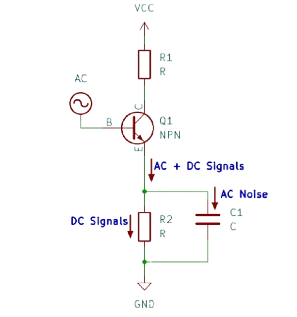
Figure 3: Bypass Capacitor in Circuits
The bypass capacitors play the roles of:
· Shunting high-frequency noise: Ensure critical components are protected against AC noise.
· Signal integrity improvement: The capacitor plays a role in preventing high-frequency interference.
· Power supply line filtering: Used to remove rippling and disallowed transients.
Bypass capacitors stabilize voltage and suppress AC noises in analog circuits and power supply lines. They also ensure clean power, crucial in RF circuits, audio amplifiers, and sensors.
Below is a table showing the differences between bypass and decoupling capacitors:
Table 2: Comparison Between Decoupling Capacitors and Bypass Capacitors
|
Specification
|
Decoupling Capacitor
|
Bypass Capacitor
|
|
Primary Function
|
Voltage stabilization and circuit section isolation. Voltage drop reduction and instantaneous voltage supply.
|
Unwanted AC noise and interference filtering.
Low-impedance path provision.
|
|
Application
|
Microcontrollers, memory, CPUs, and many other digital circuits.
|
RF circuits, analog circuits, and power supply lines.
|
|
Types of Capacitors
|
Ceramic capacitors range between 0.1uF and 10uF, and electrolytic capacitors range from 10uF and 100uF
|
Ceramic capacitors range from 10nF to 0.1uF. Sometimes, tantalum capacitors of the same range are used.
|
|
Placement
|
Near VCC and VDD pins of ICs.
|
Across signals and power supply lines.
|
|
Main Effect
|
Voltage level stabilization
|
Hogh-frequency ripples filtering.
|
Why is Decoupling Necessary?
Modern electronics require circuits with essential and reliable power delivery. Without the right decoupling, circuit performance might be limited by power fluctuations, transients, and noise.
Decoupling capacitors provide the required power integrity by managing unexpected power changes, thus giving the circuit optimal performance. Below are the main reasons why decoupling is significant in a circuit.
Power Integrity
With decoupling capacitors, voltage fluctuations are eliminated, thus ensuring that the IC circuit receives enough power for operation.
With poor power integrity, electronic systems have unpredictable behavior. A well-designed power system has well-selected decoupling capacitors. The decoupling capacitors filter noise and voltage spikes, ensuring the circuit receives smooth power.
IC Sensitivity
The latest IC technology is susceptible to noise in the power supply. If the voltages are not well filtered, the AC signal noise affects how such ICs function.
Putting decoupling capacitors near the IC inputs works well by suppressing the AC and transient noises that might be present in the circuit. Poor decoupling leads to AC failure, but proper decoupling ensures the AC receives proper voltage supply no matter what load it receives.
Types of Decoupling Capacitors
Common types of decoupling capacitors are electrolytic, ceramic, and multilayer ceramic capacitors:
Electrolytic Capacitors
Electrolytic capacitor is a type of decoupling capacitor made of an oxide film. The oxide film uses oxidizable metals such as tantalum and aluminum. The oxidizable film is the capacitor dielectric.
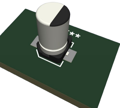
Figure 4: Electrolytic Capacitor
Electrolytic capacitors can store large amounts of power and are used in power supplies. There are two main types: water-based and solid electrolytes. Wet electrolytes can be classified as aluminum and tantalum electrolyte capacitors, while solid electrolytes include manganese dioxide, organic semiconductors, and conductive high-polymer electrolytic capacitors.
Electrolytic capacitors are used as decoupling capacitors due to the following features:
· Large, thus easy to replace when faulty.
· Suitable for low-frequency noise filtering
· Their large capacity makes them suitable for ample energy storage.
Ceramic Capacitors
Ceramic capacitors are the most widely used decoupling capacitors. This is due to their favorable electrical properties, which include high capacitance, low ESR, low ESL, best temperature stability, and broad frequency response.
When selecting a ceramic capacitor for decoupling, consider the following factors: Capacitance value, capacitance type, and Voltage value.

Figure 5: Ceramic Capacitors
Multilayer Ceramic Capacitors (MLCCs)
Multilayer ceramic capacitors (MLCCs) can be classified as special ceramic capacitors. Its unique characteristics include small size, large capacity, good voltage stability, cheaper, and flexibility in mass production use.
They are used as decoupling capacitors in consumer electronics, military, aerospace, automotive electronics, etc.
The structure of a multilayer ceramic capacitor consists of several layers of ceramic stacked on each other, with conductive metal electrodes sandwiched between them. Several multilayer ceramic capacitors exist: general-purpose, high-voltage, automotive-grade, and safety-certified MLCCs.
Features that make MLCCs suitable for decoupling include:
· High capacitance for storing enough charge.
· Low ESR, thus able to respond to voltage changes rapidly.
· It is highly reliable due to its long shelf life and low probability of failure.
· High-frequency performance allows them to operate at very high frequency while maintaining performance.
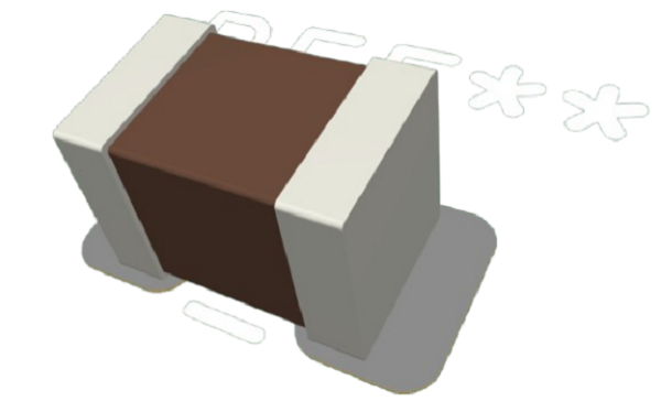
Figure 6: Multilayer Ceramic Capacitors
Decoupling Capacitor Placement
To ensure that decoupling capacitors give optimal performance, you should know where to place your decoupling capacitors and important PCB layout considerations.
Placement Strategies
· The decoupling capacitor should be placed as close to the IC input power pins as possible to ensure that the inductance loop is minimal.
· Don’t use a single capacitor. Make sure you subdivide the total capacitance into several capacitances and select the capacitors. This ensures the filtering of different frequencies.
· For uniform power supply, Ensure the capacitors are evenly distributed across the PCBs.
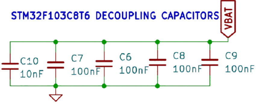
Figure 7: STM32 Evenly Capacitance Distributed Decoupling Capacitors
PCB Layout Considerations
During the process of PCB layout of the decoupling capacitors, ensure you consider the following:
· Make your signal traces wide and short. This reduces inductance and power resistance.
· Make sure that your PCB has a solid ground plane, which improves the current flow path and makes it more stable.
· Employ via placement techniques. This improves your board connectivity and minimizes impedance in capacitors.
How to Choose the Value of a Decoupling Capacitor?
The power distribution network (PDN) and the expected impedance characteristics determine the decoupling capacitor's selection. The PDN can be analog or digital.
· Low ESR and low ESL capacitors are preferred for the digital PDN. 0.1uF to 1uF capacitors are placed near the IC's power pin to filter high-frequency noise.
For low-frequency noise, 10uF to 100uF capacitors come in, while multiple capacitors connected in parallel are used to filter a wider range of frequencies.
The capacitors are placed very close to power pins and near the entry points if the capacitors are bulky.
· For analog PDN, low ESR capacitors eliminate unwanted oscillations. 1uF to 10uF capacitors filter low-frequency noise, and 10nF to 100nF capacitors suppress high-frequency noise. Electrolytic or tantalum capacitors are used for this purpose.
The capacitors are placed near power pins and distributed along the power signal traces to eliminate voltage drops in the circuit.
· Based on PDN impedance, the goal is to ensure that the fruit has very low impedance throughout all frequencies, reducing noise in the circuit. Ensure you calculate the target impedance and select the best capacitor.
Applications of Decoupling Capacitors
Decoupling capacitors are used in various areas of modern-day electronics. This includes consumer electronics, automotive electronics, and high-speed digital systems.
Consumer Electronics
Used in smartphones, gaming consoles, and laptops for maintaining a stable power flow.
Automotive Electronics
Used in ECUs, information systems, and ADAs to ensure durability and smooth power flow.
High-speed Digital Systems
Decoupling capacitors are used to build high-speed digital systems for data center embedded systems and networking hardware.
Conclusion
The article is all about understanding decoupling capacitors. Choosing the right capacitors means selecting them based on their capacitance rating, ESR, and ESL. Besides that, you have to understand various types of capacitors and how they compare with each other.
When a designer or engineer faces power integrity challenges, the focus should be on the type of capacitor and its ratings. Good capacitor selection means a good and stable power supply in the circuit. Also, understanding how to select and place your capacitor in an electronic circuit is a perfect practice for every engineer. Decoupling capacitors should be used in the right place and for the proper application.