Global high-mix volume high-speed PCBA manufacturer
9:00 -18:00, Mon. - Fri. (GMT+8)
9:00 -12:00, Sat. (GMT+8)
(Except Chinese public holidays)
Global high-mix volume high-speed PCBA manufacturer
9:00 -18:00, Mon. - Fri. (GMT+8)
9:00 -12:00, Sat. (GMT+8)
(Except Chinese public holidays)
HomePage > Blog > Knowledge Base > Current Limiting Circuits: The Ultimate Guide
Current-limiting circuits serve as important safety guardians in modern electronics and prevent potentially dangerous overheating and component failures. According to 2020 NEC/NFPA 70, this protective equipment significantly reduces fault currents compared to fixed conductors and mainly acts as a safety valve for electronic systems.
In addition, we find two main types of current limited approaches: constant current limiting and fold-back current limiting, each with unique protective properties. In particular, the foldback current limiting shows better efficiency than the constant current design. In this wide guide, we will find out how the current limiting circuits work, check the different types, and understand their important applications - from protecting sensitive data components to protecting industrial power supply.
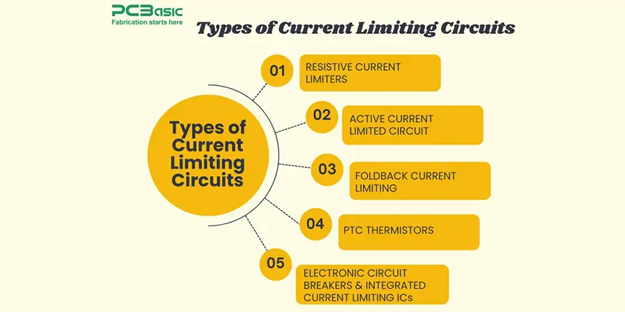
The current limiting circuits come in many different variants, designed for each specific application and security requirements. While many electronic enthusiasts recognize the basic concept, it helps to understand the nuances between different types to choose the right safety mechanism for a particular circuit.
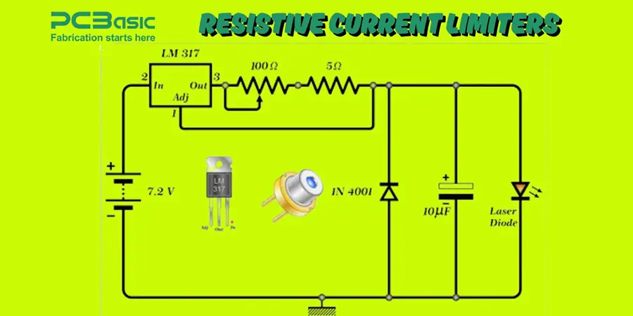
Resistive current limiters represent the simplest form when using a certain inhibitor in the chain with the load. These work on legal principles, which make a voltage drop proportional to the current. However, they constantly dissolve the power regardless of operating conditions, making them less effective than active alternatives.
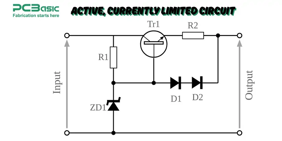
Active current limiting circuit transistors or special ICs are used as a control element. The basic transistor boundary appoints a sensing resistance that activates the transistor when the current exceeds a predetermined threshold. Several sophisticated designs include operating amplifiers for accurate power control and threshold settings.
Foldback current limiting provides a particularly elegant power supply solution. Unlike the constant power limits that maintain maximum current under an error, the foldback design reduces the output current as the fault increases in severity. This approach reduces waste of power during short circuits and protects both the load against power supply and thermal damage.
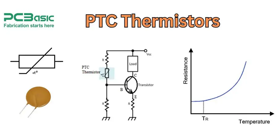
PTC (positive temperature coefficient) Thermistors protect self -registration. These components increase dramatic resistance when heated with excessive current and effectively limit the circuit. When the fault is resolved and the thermister is cooled, the normal operation starts again without manual intervention.
Electronic circuit breakers represent another advanced alternative, combining solid-state swaps with sophisticated detection circuits. These devices react to rapid size orders faster than mechanical switches, making them ideal for protecting sensitive electronics. For accurate applications, integrated current Limited IC's complete solutions with adjustable thresholds, guilty indications and automatic recovery provide. The same package in modern design includes thermal shutdown, under-voltage lockouts, and several safety mechanisms, including precise power monitoring.
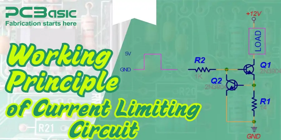
Fundamental theory behind all current limiting circuit centers for detection and intervention. These protection circuits mainly monitor the current flow and react when it exceeds the predetermined threshold. Unlike simple leaders, a current limited system introduces controlled impedance to maintain safe operations.
At its core, a current-limiting circuit relies on a sensing component to detect excess current. The sensing part measures power streams such as
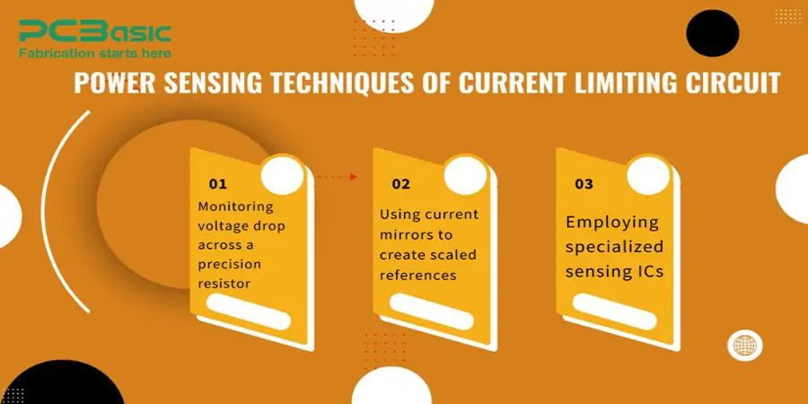
When the additional current is detected, the circuit responds by increasing the resistance or reducing effective voltage. In practice, it is usually through a transistor that switching from linear to saturation mode effectively provides impedance to the circuit.
The classic "brick wall" power limit maintains the output voltage, which reaches a predetermined limit. Then it holds the current stable, while proportionally drops to load the voltage resistance. This sudden limited action explains the surname "Brick-Wall"-the current bus set cannot exceed the specified area.
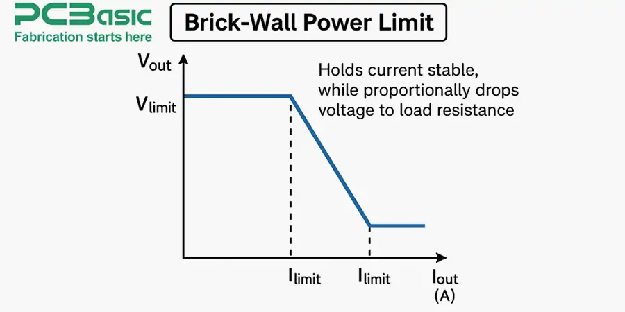
For more sophisticated safety, the fold back reduces the current as the fault deteriorates. This technique reduces the waste of current in case of failure, with a maximum disruption of about three times less than the constant power designs.
The operation can be conceived through a basic transistor-based limit. When the current creates sufficient voltage (usually 0.65V) through a sensing resistance, it activates a safety transistor. This transistor then triggers the base flow from the output transistor, which results in the collection current flowing to the load.
In addition, superconducting fault current limiters (SFCLs) transition from a superconducting state to a resistive state during faults, effectively limiting current. Meanwhile, fast-acting limits use IS-limited small charges to open the main conductor during the first increase of the error current.
In essence, all current limiting methods follow the same principle: introduce controlled resistance to prevent damaging current levels while maintaining normal operation under standard conditions.
The use of current limiting circuits provides both important advantages and remarkable disadvantages for electronic system design. Understanding these trade-offs helps engineers make informed security strategies.
Advantages of Current Limiting Circuit
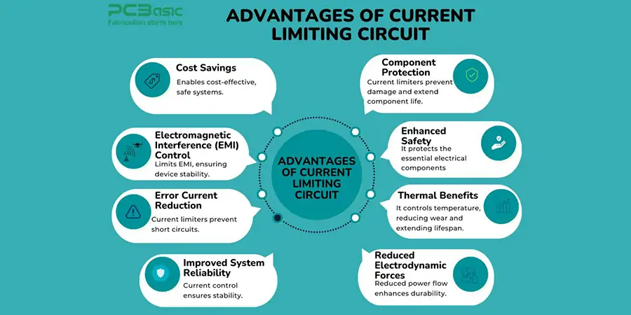
A current limiting circuit prevents damage to excessive power-sensitive components and ensures their long life. This security is important for the circuit with delicate electronics that are likely to fail due to a sudden increase.
It protects the essential electrical components, such as protective cables, switches, and contactors that lack the underlying safety. Limiting excessive current reduces the risk of overheating, fire hazards, and system errors.
By reducing the increase in total temperature in a circuit, it helps to maintain low operating temperature for components. It reduces wear and gradually expands its own operating life.
Low power flow reduces electromagnetic forces, reducing the risk of mechanical deformation in electrical connectors and collection rails. It ensures better durability and operating efficiency.
Prevention of excessive electric current helps maintain a stable electrical system and reduces unexpected errors. It increases the general reliability and efficiency of industrial and commercial applications.
Current limiting circuit line-to-line and line-to-hill help control error streams in cases of errors. This reduces the possibility of a short circuit and damages the connected component
By limiting additional electricity currents, these circuits reduce EMI and prevent disturbance of almost sensitive electronic devices. It is especially important in the atmosphere with accurate equipment and communication systems.
The technology allows for the use of small, lower ranked switches, which reduces the cost of replacing equipment and electric cabinets. This makes electrical systems more cost-effective without compromising safety.
Disadvantages of Current Limiting Circuit

Here are the disadvantages of current-limiting circuits.
1. Increased Complexity and Cost
The design of the current limiting circuit combines complexity and costs, especially when two transistors and a sensing resistor use traditional configurations.
2. High Set Points and Tolerance
To accommodate the expected operations, the traditional cycle requires high set points, leading to a tolerance of 20-30% from the expected current limits. It introduces impurities to performance.
3. Significant Heat Generation
During current limited operations, these circuits produce significant heat. In power applications, this heat can be wasted 5-10W, which is undesirable.
4. Temperature Sensitivity
The performance of the circuit is sensitive to temperature changes. For example, with amplifiers, the current limited point can shift or vary to about 0.3% per degree Celsius, leading to volatility in the current border setting.
5. Challenges with Foldback Current Limiting
Foldback current limiting, while useful for circuit protection, struggles with non-linear loads like incandescent lamps or motors, which may experience high startup currents. This can reduce the effectiveness of the current limiting circuit in such scenarios.
These points highlight the trade-offs in performance and efficiency when using current-limiting circuits.
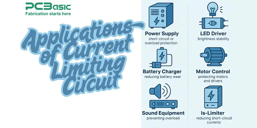
Current limiting circuits find widespread use in many industries and serve important safety tasks in many electronic devices and systems. These protective mechanisms maintain stable operations during general use and error situations to prevent damage to sensitive components.
In power supply, current limits serve as necessary protection against short-circuit or overload conditions, which causes the power supply and circuit to be operated. Almost all regulated power supplies include the current limited as a standard function, with these circuits, especially used on linear power supply.
LED drivers implement current limiting to deliver consistent power to LEDs, maintaining brightness stability while protecting against voltage fluctuations that could cause damage. Similarly, the Battery Charger uses current limited to reduce battery decrease, as well as improve safety and operating efficiency.
Motor control applications benefit from the current limiting circuit by preventing harmful violations that can damage both motors and driver's circuits. This protection ensures reliable operation under varying load conditions. Sound equipment, in the same way, receives protection against current limits, which protects speakers and amplifiers against possible damage caused by overload or short circuit.
The industrial environment uses special current boundaries such as Is-limiter, which has been implemented with success in more than 2500 stations in 70 countries. These fast-acting units significantly reduce short-circuit currents during the first increase, protecting system components from damage.
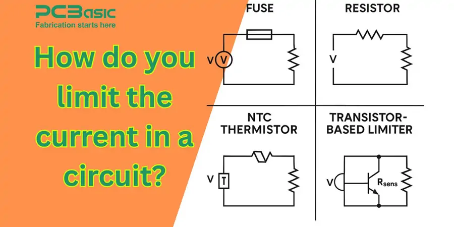
Electronic circuits have several practical methods to apply the current limited and provide unique benefits based on each application requirements. When choosing a limited approach, consider factors such as circuit complexity, cost barriers, and security levels.
Passive Components for Current Limiting
Fuses represent perhaps the simplest form of current limiting, though they're single-use devices that must be replaced after activation. Simply connected in series with the load, they'll blow when the rated current is exceeded, completely cutting off power to protect downstream components.
Resistors offer another straightforward method, working on Ohm's Law principles. To calculate the appropriate resistor value: R = (Vsupply - Vdrop) / I, where Vsupply is your source voltage, Vdrop is voltage across the load, and I is your desired current limit. For example, with a 5V supply and 4.5V minimum load requirement, a resistor of (5-4.5)/0.1 = 5Ω would limit current to 100mA.
Negative Temperature Coefficient (NTC) thermistors effectively limit initial surge currents. These components feature high resistance when cold, gradually decreasing as they warm up, making them ideal for inrush current protection.
Active Current Limiting Approaches
For more precise control, transistor-based limiters utilize a sensing resistor (Rsens) that activates a protection transistor when voltage across it reaches approximately 0.65V. The maximum current is calculated as 0.65/Rsens. With Rsens = 0.33Ω, the current would be limited to roughly 2A.
Current limiting diodes (CLDs), alternatively known as constant current diodes, maintain a steady current regardless of voltage variations—similar to how zener diodes regulate voltage. These two-terminal devices typically consist of a JFET with the gate shorted to the source.
Integrated circuits designed specifically for current limiting offer the most sophisticated solution, providing adjustable thresholds plus additional protections like thermal shutdown. The LM317 configured as a current limiter uses a simple equation: Ilimit = 1.25V/R, where R determines the current threshold.
Notably, when designing current limiters for sensitive applications requiring minimal voltage drop, specialized op-amp circuits can provide limiting with drops under 100mV before limiting activates.
When designing current-limiting circuits, several factors require careful attention. First, determining the maximum allowable current represents the initial step, as this guides component selection and limit settings. Additionally, load type significantly impacts circuit design choices, as resistive loads may require different limiting approaches than inductive or capacitive loads.
Voltage drop across limiting components must be accounted for to ensure proper operation of the protected circuit. Furthermore, thermal considerations are crucial, as current limiting components convert electrical energy to heat, necessitating components with adequate power ratings. Response time, efficiency, and temperature range all warrant careful consideration for optimal protection and performance.
Current limiting circuits stand as essential safeguards across modern electronics, from simple LED drivers to complex industrial power systems. Through this comprehensive guide, we explored various current limiting approaches, each offering unique protective characteristics suited for specific applications.
Basic resistive limiters provide straightforward protection, while advanced solutions like foldback current limiting deliver superior efficiency with minimal power dissipation. Active limiting circuits using transistors or specialized ICs offer precise control and additional protective features, making them ideal for sensitive electronic applications.
The practical implementation methods we discussed range from simple passive components to sophisticated integrated circuits. These solutions help engineers select appropriate protection mechanisms based on their specific requirements, whether designing power supplies, motor controllers, or battery charging systems.
Understanding current limiting circuits proves crucial for any electronics professional or enthusiast working with power systems. The knowledge of various limiting techniques, their advantages, and implementation methods enables better design decisions and helps create more reliable electronic systems.
This guide serves as a foundation for implementing effective current protection in electronic designs. As technology advances, current limiting circuits will continue playing a vital role in safeguarding electronic components and ensuring system reliability.

Assembly Enquiry
Instant Quote
Phone contact

+86-755-27218592
In addition, we've prepared a Help Center. We recommend checking it before reaching out, as your question and its answer may already be clearly explained there.
Wechat Support

In addition, we've prepared a Help Center. We recommend checking it before reaching out, as your question and its answer may already be clearly explained there.
WhatsApp Support

In addition, we've prepared a Help Center. We recommend checking it before reaching out, as your question and its answer may already be clearly explained there.
