Global high-mix volume high-speed PCBA manufacturer
9:00 -18:00, Mon. - Fri. (GMT+8)
9:00 -12:00, Sat. (GMT+8)
(Except Chinese public holidays)
Global high-mix volume high-speed PCBA manufacturer
9:00 -18:00, Mon. - Fri. (GMT+8)
9:00 -12:00, Sat. (GMT+8)
(Except Chinese public holidays)
HomePage > Blog > Knowledge Base > Circuit Board Components: How to Identify Components on a PCB
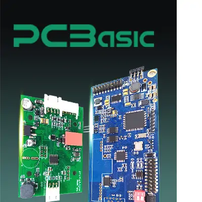
Time is money in your projects – and PCBasic gets it. PCBasic is the pcb assembly company that delivers fast, flawless results every time. Our comprehensive PCB Assembly Services include expert engineering support at every step, ensuring top quality in every board. As a leading PCB Assembly Manufacturer, we provide a one-stop solution that streamlines your supply chain. Partner with our advanced PCB Prototype Factory for quick turnarounds and superior results you can trust.
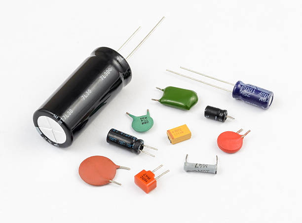
Capacitors are the second most widely used circuit board component after resistors. Their function is to store electrical charge and smooth voltage in a circuit temporarily. Capacitors utilize two conductive plates separated by an insulating material known as a dielectric. Different types of dielectric materials provide various capacitance values.
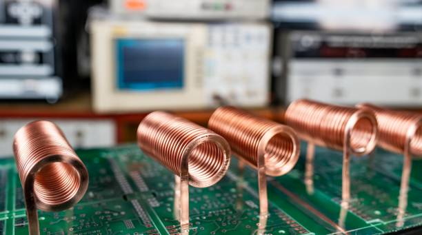
Inductors are another important component found on circuit boards. Similar to capacitors, inductors store energy, but instead of electric charge, they store energy as a magnetic field. Inductors are coils of wire wrapped around a core, often a ferromagnetic or ferrite material. As current passes through the coil, it creates a magnetic field proportional to the current and number of turns in the coil.
Inductors have the property of resisting changes in current flow, making them integral to functions like filtering noise and smoothing fluctuations in alternating current circuits. Common inductors seen on PCBs include wire wound, multilayer, and shielded inductive components available in various inductance values.
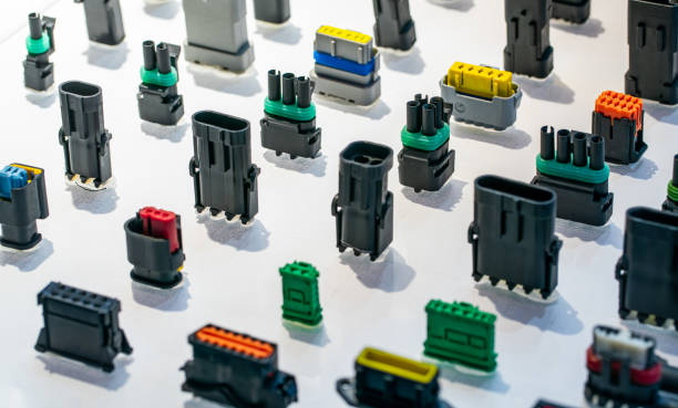
Connectors are essential interface components that allow boards to connect with off-board circuitry and other devices. Common connector types used in electronics include pin headers, wire-to-board terminals, ribbon cables, board-to-board headers, and external connectors like USB, HDMI, and modular jacks.
Connectors must be rugged enough to make and break connections during assembly/service life cycles. Their pin-out configurations comply with interface standards to enable integration into systems.
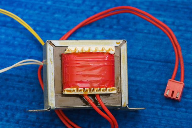
Transformers are circuit board components used to transfer electrical energy from one circuit to another through electromagnetic induction. They are composed of two or more coils of wire wrapped around a shared core. Varying the number of coil windings changes the voltage transferred according to the transformer equation.
Signal isolators use transformers to isolate sensitive circuits from noise-prone environments electrically. On PCB boards, transformers appear as discrete through-hole or surface-mount components dedicated to AC voltage conversion applications.
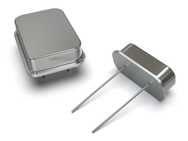
Crystal oscillators are timing elements found on circuit boards. They contain a piece of piezoelectric material, usually quartz crystal, that physically oscillates at an exact frequency when an electric current is applied. This oscillation produces a periodic electronic signal that serves as a reference clock source.
Onboard clocks are crucial as modern circuits rely on precise timing to function correctly. The crystal oscillates reliably to keep microcontrollers synchronized and ensure processes occur at the right intervals. Their stability and small size make crystals well-suited for applications requiring accuracy, like computers and phones. Crystals typically oscillate between 1MHz and 100MHz, falling within frequency ranges needed by different chips.
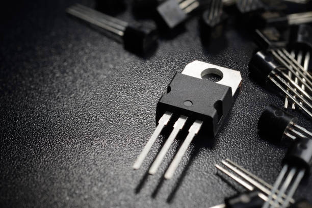
Transistors are fundamental electronic components that act as switches or amplifiers. The most widely used type is the bipolar junction transistor (BJT), which has three terminals: base, collector, and emitter.
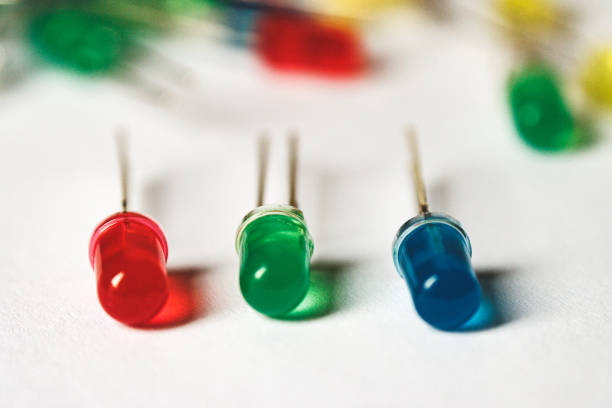
Diodes are one-way electronic valves that allow current to flow in only one direction. The most common type is the light-emitting diode (LED), which emits light when current flows through it in the forward bias direction from the anode to the cathode. On circuit boards, diodes protect components by blocking current flowing in the wrong direction, preventing damage. LEDs are also widely used as indicator lights.
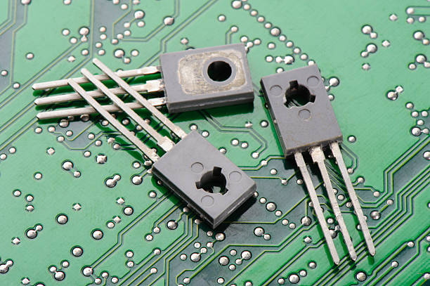
SCRs are semiconductor devices similar to diodes and transistors. Also known as thyristors, they have four alternating layers of semiconductor material that allow current flow in only one direction when a trigger signal is supplied to the gate terminal. This triggers the SCR into conducting mode.
On circuit boards, SCRs are commonly used components as electrically controlled switches in applications like light dimmers, where they regulate current flow. Their conducting once-triggered property makes SCRs well-suited to switching higher currents with only low-power control signals.
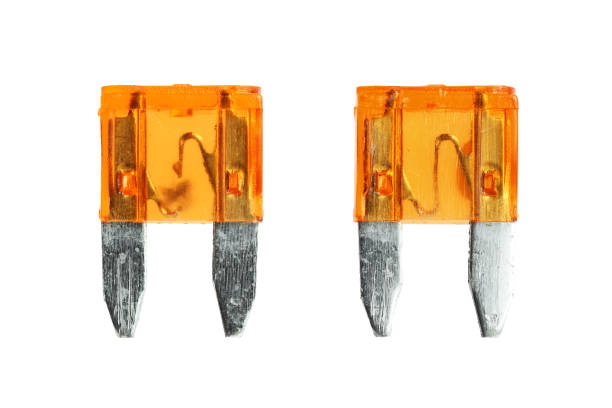
Fuses are safety devices on circuit boards to protect other circuit board components and wiring from overcurrent damage. They contain a fine wire or strip of metal that melts when too much current passes through. This interrupts the circuit to prevent components from burning out.
Fuses come in various amperage ratings and physical forms like glass cylinders or electronic surface mount. Their inclusion is vital as it limits damage from short circuits or power surges to only the fuse, avoiding cascading failures across the entire board.
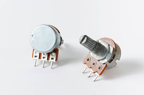
Potentiometers are variable resistors whose resistance can be changed by an external mechanical device like a dial or slider. On circuit boards, common implementations are single-turn potentiometers adjusted through a knob or linear potentiometers with slider bars. Their versatility enables real-time adjustment of circuit parameters like volume controls.
During production, multi-turn potentiometers allow the calibration of circuits. Potentiometers see widespread use as any circuit requiring a continuously adjustable input value can make use of a potentiometer's varied resistance.
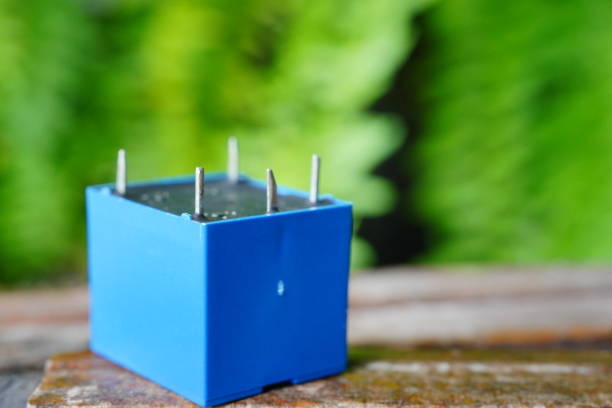
Relays are electrically operated switches supplemented with coils of wire that create magnetic fields. On circuit boards, relays are parts that allow low-power input signals to control circuits handling higher currents or voltages safely. When engaged, the magnetic field pulls a set of contacts closed to complete a separate circuit.
With the multitude of parts present on any given PCB, it is important to understand how they are classified to identify components and understand their purpose. In general, the circuit board components are divided into mechanical and electrical. Each classification works differently and is specific to perform critical functions in PCB design and manufacturing. Let's take a closer look at each.
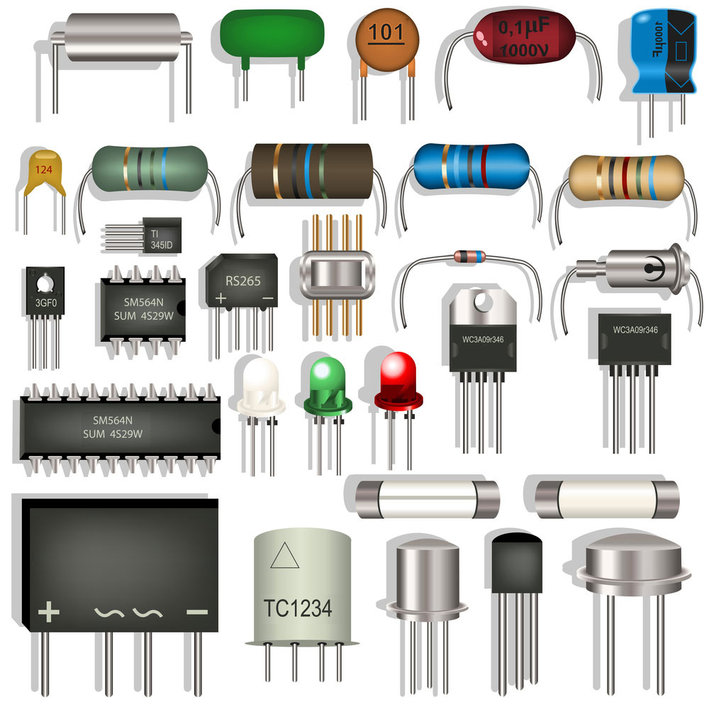
The electrical components of circuit boards are the parts that handle the flow of electricity through the board. They allow current to pass between different areas of the circuit. Electrical circuit board components differ from mechanical components in that mechanical parts are used for physical structure and connections rather than electrical functions.
Mechanical components provide support and connection points for attaching electrical parts but do not regulate or control electricity flowing through the circuit. Electrical components are what make the circuit functional by controlling or directing current flow.
There are two main types - passive and active components. Let's take a closer look at both of them.
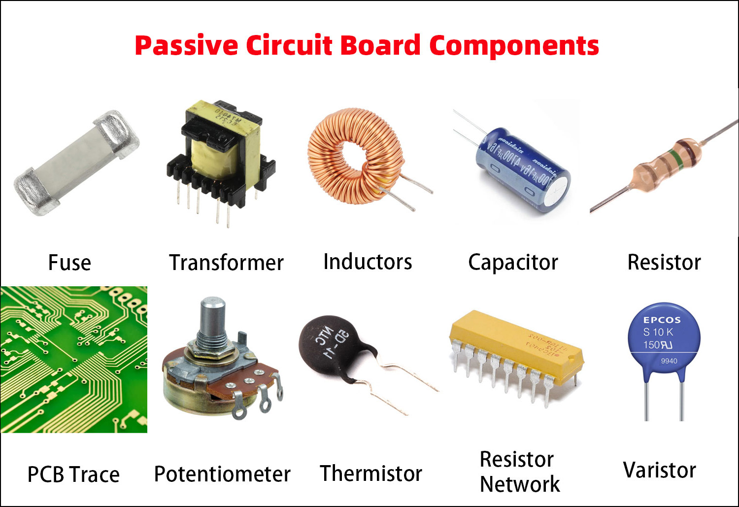
Passive electrical components are an essential part of any electronic circuit. They are defined as components that do not require a power source to function, unlike active components that do require a power source. Passive components alter the flow of electric current through a circuit without using any power.
They provide simple but crucial roles in shaping electric signals and directing power in both analog and digital circuits.
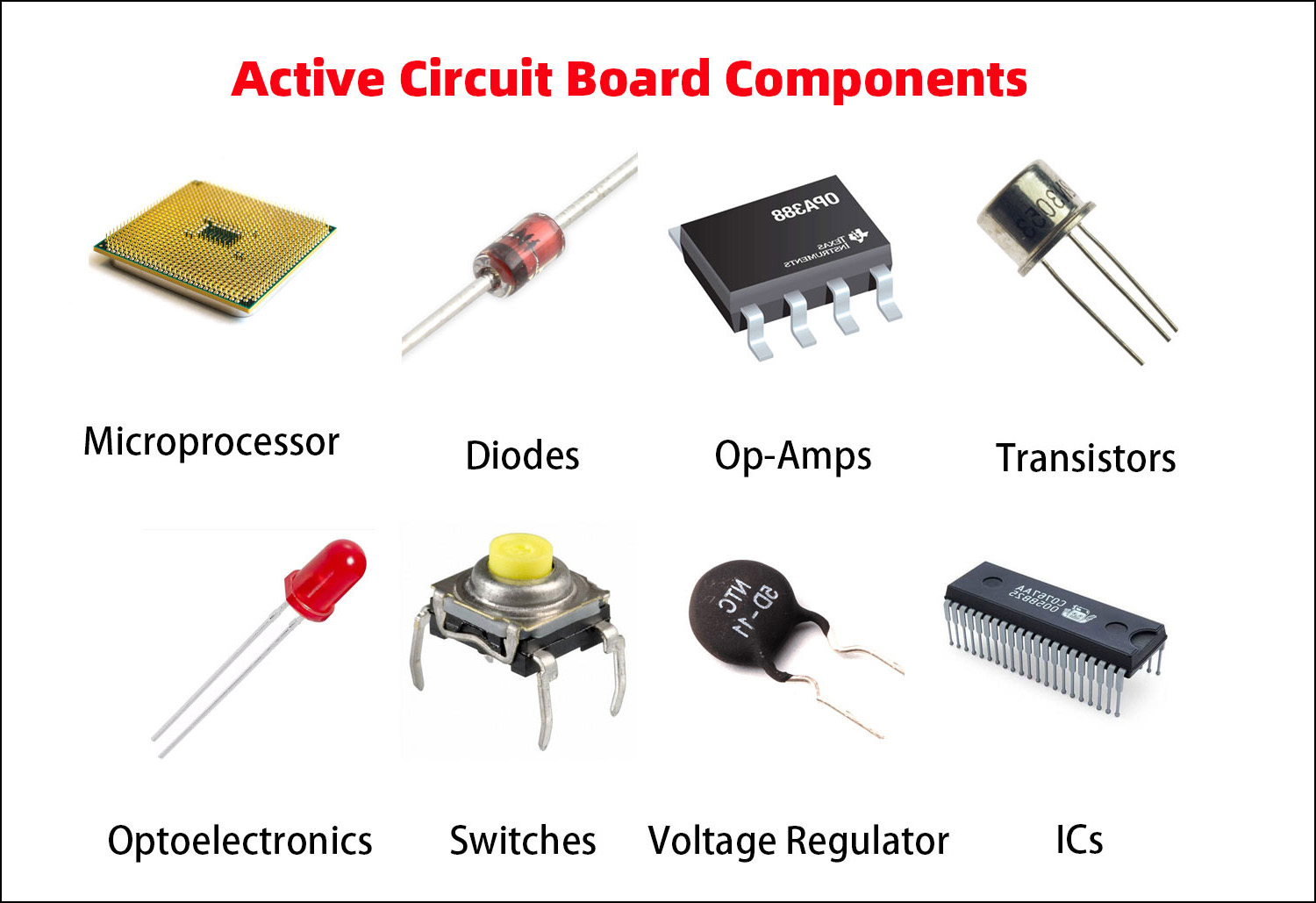
Active components are a crucial part of any electronic printed circuit board (PCB) as they are able to generate, control, modify, and strengthen electrical signals. Unlike passive components that can only attenuate, store, or release energy, active circuit board components require external power to function and are capable of controlling or amplifying signals.
Here are some helpful tips for determining what each part is and what it does.
The first step is to examine the entire board to determine its overall function. Look for any part numbers, model names, or descriptive text printed on the board itself that can provide context. Is it a main system board, add-on module, or dedicated controller?
Boards intended for computers, industrial machines, and medical equipment often have standardized layouts and components for their functions. Taking note of a board's purpose will help narrow down what to expect from it.
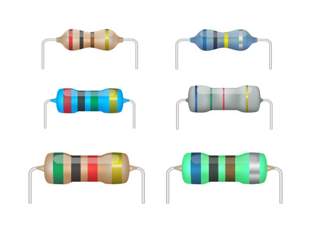
Passive components like resistors, capacitors, and inductors are good places to start identification due to their consistent designs. Resistors may have color-coded bands indicating resistance value. Look closely, as some have all-numeric printing instead.
Capacitors are marked with the letter C followed by capacitance rating in farads or a coded system of numbers and letters. Inductors resemble small coils labeled L. Take time to examine passive parts' physical features, labels, and relative locations for clues.
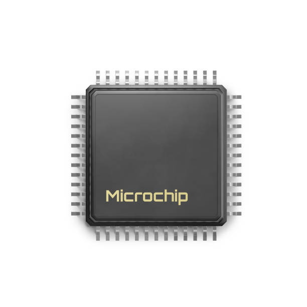
Integrated circuits (ICs) are complex active devices that condense multiple transistors and other components onto a single silicon chip. They often have part numbers or manufacturer markings printed right on the surface that can be researched.
Depending on age, an IC may simply have a functional label like 7400 instead of a detailed number. ICs' varying shapes and pin configurations also provide clues. Give ICs extra scrutiny, as correct identification reveals critical roles
Transformers, relays, connectors, and diodes are generally labeled with standardized initials like T, K, J, or D. Transformers resemble small multiply-wound coils. In contrast, relays look similar to an electrically operated switch.
Diodes may have stripe patterns on cylindrical packages indicating polarity. Batteries are usually stamped BT. Discrete parts don't hold as many internal details as ICs, but understanding common symbols aids recognition.
Some circuit boards include alphanumeric reference designators directly on traces near each part for reference. Though formats vary, these abbreviations paired with placement point to a circuit board component's identity and purpose within the circuit. Take advantage of clearly marked references when deciphering obscure components' functions.
| Designator | Components |
|
ATT |
Attenuator |
| BR | Bridge Rectifier |
| BT | Battery |
| C | Capacitor |
| CB | Circuit Breaker |
| CN | Capacitor Network |
| DC | Directional Coupler |
| D | Diode |
| F | Fuse |
| G | Oscillator |
| IC | Integrated Circuit |
| J | Jumper or Jack |
| K | Relay or Contactor |
| L | Inductor |
| LED | Light-emitting Diode |
| LS | Loudspeaker |
| MOV | Metal Oxide Varistor |
| P | Plug |
| POT | Potentiometer |
| PS | Power Supply |
| Q | Transistor |
| R | Resistor |
| S or SW | Switch |
| TB | Terminal Block |
| TC | Thermocouple |
| TP | Test Point |
| TR | Transducer |
| T | Transformer |
| U | Integrated Circuit |
| VR | Variable Resistor |
| X | Transducer |
| XTAL | Crystal |
| Z | Zener Diode |
| ZD |
Zener Diode |
If a circuit board component remains unidentified after thoroughly examining physical properties, labels, and reference designators, turn to other resources like manuals, diagrams, or online component databases with searchable part numbers before making assumptions.
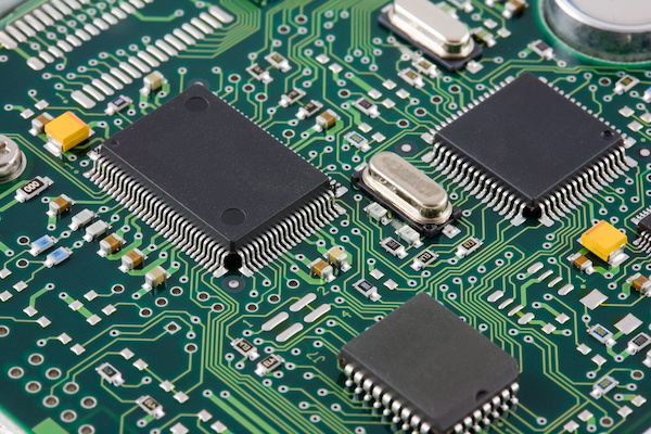
Components are connected on a printed circuit board through a network of pathways called traces. Traces are thin copper strips laminated between layers of a non-conductive substrate like fiberglass.

Assembly Enquiry
Instant Quote
Phone contact

+86-755-27218592
In addition, we've prepared a Help Center. We recommend checking it before reaching out, as your question and its answer may already be clearly explained there.
Wechat Support

In addition, we've prepared a Help Center. We recommend checking it before reaching out, as your question and its answer may already be clearly explained there.
WhatsApp Support

In addition, we've prepared a Help Center. We recommend checking it before reaching out, as your question and its answer may already be clearly explained there.
