Global high-mix volume high-speed PCBA manufacturer
9:00 -18:00, Mon. - Fri. (GMT+8)
9:00 -12:00, Sat. (GMT+8)
(Except Chinese public holidays)
Global high-mix volume high-speed PCBA manufacturer
9:00 -18:00, Mon. - Fri. (GMT+8)
9:00 -12:00, Sat. (GMT+8)
(Except Chinese public holidays)
HomePage > Blog > Knowledge Base > Arduino Nano Pinout Explained: Layout, Features, and Board Comparison
The Arduino Nano is an ATmega-based microcontroller board that is incredibly small in size and ideal for designing portable electronic circuits. Many people choose it because it’s relatively compact and quite versatile for gamers, amateurs, students, or professionals.
Understanding this kind of board is required to gain benefit from it. Hence, familiarizing with the pinout of this board is crucial. The pinout here refers to the map of the Nano along with the role of pins through which it interfaces with other devices, including sensors, LEDs, and motors, among others.
Now let us look at all the Arduino Nano pinout descriptions in detail to enable improved use of this board in projects.
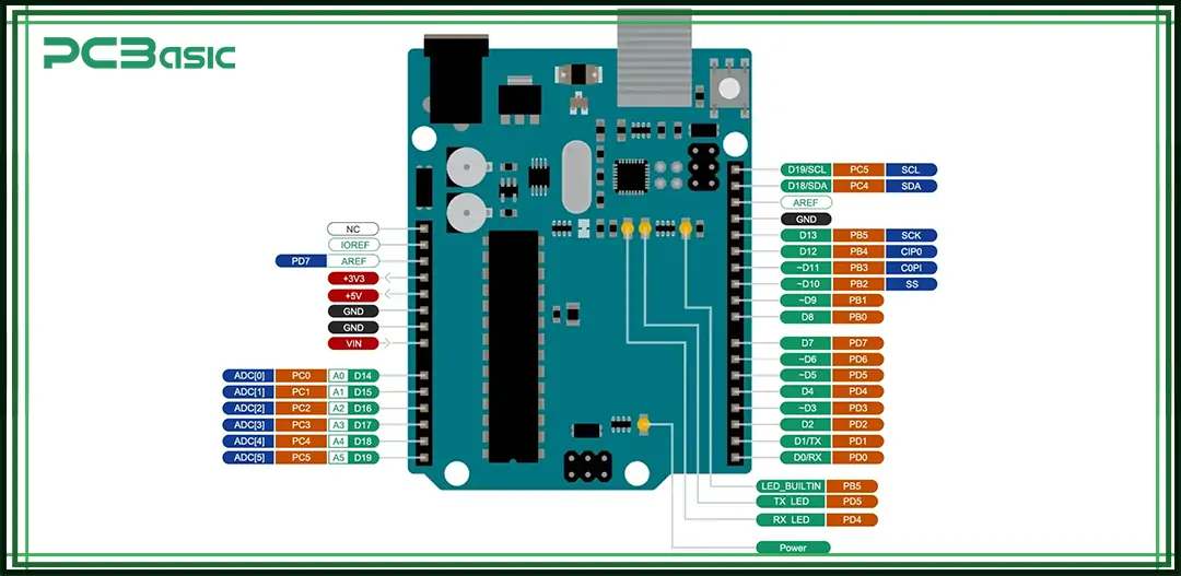
Arduino Nano is a small form factor and power-packed microcontroller board that has been welcomed by electronics professionals, hobbyists as well as students. As its name suggests, Nano was created by Arduino. It is cc'd by the same team as Arduino Uno, but this one is equipped with the ATmega328P control chip and is smaller than this board. This makes it particularly ideal for use where physical space is a major constraint for hardware designers, as is often the case in wearables, robots, and other subtracted chip-embedded systems.
All the pins of an Arduino board are numbered and have names different from one another. The first hexadecimal number shows the location of the pin, and the second hexadecimal number describes the function of the pin as a digital input/output, an analog input, or a power supply. Secondly, a pin description gives more specifics about the pin, especially the voltage level and the current consumption.
For example, the Arduino Nano contains a total of 30 pins, where there are 22 pins that are assigned the input/output roles. Of these, 14 can be configured for Digital I/O with various operations programmed to occur in the pin. This flexibility gives users control over using the LEDs, motor, and sensors, among other devices.
Every person working with the Arduino boards needs to learn about pinouts such as the Arduino Nano. Here are some key reasons why this knowledge is important:
• Correct Connections: The second reason is that if the person knows the pinout, then he or she can connect all the components properly. These are nameless, but each pin has a specific role that it plays in a circuit, for example, input or output. Accidentally soldering an element to the wrong terminal does not make it function in the right way. If connected incorrectly, it could damage or destroy the board.
• Efficient Programming: As you get to know the pins, you can easily and effectively write your code since you know which pin does what. You will be aware of which pins are suitable for connecting sensors, motors, or any other device. Which in turn leads to fewer programming errors and a more refined approach to program development.
• Maximizing Functionality: The Arduino Nano has many pins given different functions as follows: While there are pins that accept analog signals, there are other pins that accept only digital signals. With the dimension of the pinout above, one is in a position to exploit the full potential of these features in their projects.
• Troubleshooting Issues: Even If something is wrong in your project, you can work effectively once you understand the pinout. One is that you can easily determine whether some components have been wired to the right pins and whether or not they work as expected.
• Learning and Experimentation: In the view of beginners, an introduction to the pinouts has great potential. It provides the opportunity to manipulate concrete components and to study their connection with the help of the Arduino board. What is more, it is significant to use such hands-on tools in order to develop abilities in electronics as well as in programming.
While there are significant differences in the physical form and package, the Uno or Mega or any other Arduino pin connections are considerably different from an Arduino Nano. It shares most of the fundamental features of the board but has a dense pin layout, whereas the Nano is physically smaller. Due to its compact design, it is suitable for use in areas where space is a limiting factor.
• The essential variation is that the headers on the Nano are male and meant to be soldered, while the Uno, most of the time, uses female headers. Also lacking on the Nano board is a standard barrel jack for power supply; instead, it uses a mini USB port or VIN pin.
• The second difference relates to the number of pins as well as its schematic. Despite the fact both have the same 14 digital pins and 6 analog pins, their positions differ slightly. The pins on the Nano are located along two sides, as shown, to ensure it is more compact and less cumbersome on the breadboard. These differences make the Nano the ideal board for small, portable, or embedded system applications than boards such as the UNO mega.
Arduino Nano is a small-sized microcontroller board developed for those projects that require less surface area. However, for its size, it provides quite a number of features that can support different tasks.
• Microcontroller: It is operated by the ATmega328P, which is efficient for controlling inputs and outputs and making calculations of results.
• Compact Size: The Nano has dimensions of 45mm x 18mm, so it will suit a range of applications where space is an issue.
• Power Supply: It can be charged through the USB port or by an external supply of 6-12V.
• Input/Output Pins: It has a total of 14 digital pins and 8 analog pins through which you can interface several devices.
• PWM Support: PWM control is possible on 6 pins, and all 6 are digital pins suitable for managing appliances such as motors and LEDs.
• Communication: UART, SPI, and I2C are the interfaces that the Nano uses in interaction with other devices.
• USB Connection: For programming, the Arduino Board has a mini Universal Serial Bus or USB-C port.
• Built-in LEDs: It has an integrated light light-emitting diode on pin number 13 of the digital pin that can be very useful during the testing process.
These features make the Arduino Nano to be comprehensive for all the learners and even the experts. Due to its size, it is portable, and because of its strong operating features, it can execute multiple electronics projects.
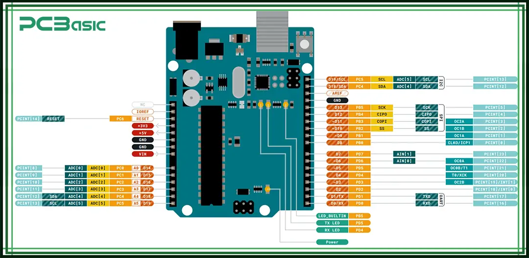
The Arduino Nano has a specific set of technical features that allow it to become an effective instrument for diverse electronic creations. Here are the key specifications:
|
Specification |
Details |
|
Microcontroller |
ATmega328P |
|
Clock Speed |
16 MHz |
|
Operating Voltage |
5 V |
|
Input Voltage (Recommended) |
7-12 V |
|
Digital I/O Pins |
22 (14 usable) |
|
PWM Digital I/O Pins |
6 |
|
Analog Input Pins |
8 |
|
Flash Memory |
32 kB (2 kB used by Bootloader) |
|
SRAM |
2 kB |
|
EEPROM |
1 kB |
|
DC Current per I/O Pin |
40 mA |
|
DC Current on 3.3V Pin |
50 mA |
|
Size |
43.2 mm x 17.8 mm |
|
Weight |
7 g |
• The Nano has a constructed LED connected to the digital pin #13, allowing for simple testing and debugging.
• It has I2C, SPI, and USART interfaces, which enable it to connect with several devices on a computer.
• The analog pins can have 10 bits, therefore allowing reading values from 0 to 1023.
 About PCBasic
Time is money in your projects – and PCBasic gets it. PCBasic is a PCB assembly company that delivers fast, flawless results every time. Our comprehensive PCB assembly services include expert engineering support at every step, ensuring top quality in every board. As a leading PCB assembly manufacturer, we provide a one-stop solution that streamlines your supply chain. Partner with our advanced PCB prototype factory for quick turnarounds and superior results you can trust.
The Arduino Nano pinout shows how each pin is used; therefore, the arrangement of the pins of the Arduino Nano determines their usage. Clarity of this structure is important for correct external elements interconnection and for optimization of the board’s potential. The following is a list of pins on the Arduino Nano.
Nano has a total of 30 pins, all of which have a specific function. Of the total 28 pins of the Arduino Nano, 22 of them are pins for input and output operations. Here's a breakdown of these pins:
|
Pin Number |
Pin Name |
Description |
|
1 |
TX / D1 |
Digital IO Pin 1 (Serial TX) |
|
2 |
RX / D0 |
Digital IO Pin 0 (Serial RX) |
|
3 |
RST |
Reset (Active LOW) |
|
4 |
GND |
Ground |
|
5 |
D2 |
Digital IO Pin 2 |
|
6 |
D3 |
Digital IO Pin 3 (PWM) |
|
7 |
D4 |
Digital IO Pin 4 |
|
8 |
D5 |
Digital IO Pin 5 (PWM) |
|
9 |
D6 |
Digital IO Pin 6 (PWM) |
|
10 |
D7 |
Digital IO Pin 7 |
|
11 |
D8 |
Digital IO Pin 8 |
|
12 |
D9 |
Digital IO Pin 9 (PWM) |
|
13 |
D10 |
Digital IO Pin 10 (PWM) |
|
14 |
D11 |
Digital IO Pin 11 (SPI, PWM) |
|
15 |
D12 |
Digital IO Pin 12 (SPI) |
|
16 |
D13 |
Digital IO Pin 13 (SPI) |
|
17 |
3V3 |
Power (3.3V) |
|
18 |
AREF |
Analog Reference |
|
19 |
A0 |
Analog Input Pin 0 |
|
20 |
A1 |
Analog Input Pin 1 |
|
21 |
A2 |
Analog Input Pin 2 |
|
22 |
A3 |
Analog Input Pin 3 |
The In-Circuit Serial Program, commonly referred to as the ICSP interface on the Arduino Nano, is useful in programming the microcontroller. Here are the pins associated with the ICSP connector:
|
Pin Name |
Description |
|
MISO |
Master In Slave Out |
|
MOSI |
Master Out Slave In |
|
SCK |
Serial Clock |
|
RESET |
Reset (Active Low) |
|
GND |
Ground |
|
VCC |
Supply Voltage (5V) |
Arduino Nano can be powered in several forms and this makes it even more suitable for any project. Here are the main methods to power the board:
• USB Connection: Of the ways to power the Arduino Nano, one of the easiest is through the mini-USB or USB-C port. The Nano is controlled through a connection with your computer or a USB adapter; It gets its power as well as code through the USB. This is the most frequent approach for testing/programming the board in one way or the other.
• External Power Supply (RAW Pin): You can also input power to the Nano externally; this would see you use a power supply. To do this, lead a 6-12V power source to the RAW pin. This voltage will be regulated by the board's integrated voltage regulator to give 5V to the board. These electronic components and this method is suitable for battery compounded projects.
• 5V Pin: In case you have a constant 5V power source, then adding it directly to the economy 5V pin is advisable. This removes the on-board voltage regulator from the equation and instead presents a far more efficient unit of power. However, make sure that the voltage being supplied does not fluctuate and should at most be 5V, as anything higher may destroy the board.
• 3.3V Pin: If you need the input voltage, which is 3.3V, there is the 3.3V pin on the Nano available for use. However, note that this pin is not to provide voltage to the board but simply to provide signals to it. Basically, it is used in low voltage components and is rarely used in the 'large' scale electronics.
In performing its functions, the Arduino Nano has several ports or interfaces that can allow it to interact with other devices, such as sensors, displays, or even other microcontrollers. These interfaces help in easy connection to many devices to work with Nano in different projects. Here are the main communication interfaces available on the Arduino Nano:
The primary mode of communication is through the USB connection option. The Nano has a small, Type B mini-USB port on the bottom of the board, which makes it easy to connect to your computer: the board uses serial communication to upload code and to communicate with your computer when it is plugged in. This also enables the Nano to send and receive data with the computer, as is depicted in the subsequent sections.
The Nano has two dedicated pins for UART communication: The first is Transmit (TX), while the second one is Receive (RX). These pins make it possible for the Nano to interface with other devices that have RS232 interfaces, including GPS, Bluetooth modules, and other microcontrollers.
I2C is a two-wire interface widely used to enable multiple devices to transmit on signal lines and is present in the Nano. On the Nano PCB, there are two pins for I2C, namely, SDA (Data) and SCL (Clock). This interface is often employed for using sensors, displays, and other peripherals and is available in numerous options to handle distinct demands.
The Arduino Nano supports SPI, a faster protocol that enables the board to interface with other devices, such as SD cards, sensors, and display devices. The SPI pins of the Nano are MISO, MOSI, SCK, and SS pins are indicated below:
Besides digital communication, the Arduino Nano can also share data with analog devices as well. The analog pins can take data from the sensors, which give constant signals like temperature sensors, light sensors, or potentiometers.
This is because you may come across some challenges whenever you are using the Arduino Nano concerning the pinout. Here are some common problems and tips on how to troubleshoot them:
• Incorrect Pin Connections: If your components are not performing well, then you should verify the pins. Make sure each pin corresponds with the right part. For example, if you are reading an analog value, then make sure that you are connected to the analog pin; if you are using it as a switch, then connect the sensor to the digital pin.
• Power Issues: If the board is not powering up, then one needs to make sure that the power is indeed connected. Check if everything is alright with the USB cable or if the power supply is an external one, then check that the voltage level is within the recommended levels (RAW pin voltage – 6-12V, 5V pin voltage – 5V). When powering up the board with 5V, ensure they don't go above this voltage as it may damage the board.
• Unresponsive Board: If it does not respond when uploading code, the connection to your computer should be checked as well as the correct board and port under tools of the Arduino IDE. In addition, you may want to press the reset button of the Nano immediately before uploading the code to the board.
• Broken or Faulty Pins: If a given pin is dead, it may be damaged. In this case, swap one pin with the other and check you will not get the same problem. Also, examine the board for any features such as bent pins, areas that are blackened through overheating, etc.
• Software Debugging: You should debug your code by going to the Tools menu and then selecting the Serial Monitor in the Arduino IDE. It can help find out whether there is a problem with your code that is causing a problem with pin functions. It is advised to add Serial.print() statements to favorite pins so that you can check step by step the values that are coming from pins.
Before selecting an Arduino board for your project, you should know more about the Arduino Nano board versus Arduino UNO or Arduino Mega. The Arduino weaves all three boards under its belt, but these come with different characteristics that suit different projects. The following diagram indicates how the Arduino Nano is placed between the Arduino UNO and Arduino Mega.
The Arduino Uno and Arduino Nano share many similarities, but they also have distinct differences:
|
Feature |
Arduino UNO |
Arduino Nano |
|
Size |
2.7" x 2.1" |
1.7" x 0.73" |
|
Weight |
25 g |
7 g |
|
Digital I/O Pins |
14 (6 PWM) |
14 (6 PWM) |
|
Analog I/O Pins |
6 |
8 |
|
Power Supply Options |
DC power jack and USB |
USB or VIN pin only |
|
USB Port Type |
Standard USB |
Mini USB |
|
Flash Memory |
32 kB (0.5 kB for Bootloader) |
32 kB (2 kB for Bootloader) |
The Arduino Uno is physically larger and comes with a better power supply option in the form of a DC power jack. It is ideal for typical applications on any project where the area of coverage is not a constraint. For instance, the normal size of Nano may be limited in projects that require a large form factor, but it will work appropriately for projects like wearables or drones, among others. Besides this, the Nano also has two extra analog input pins, and this can be advantageous to projects with many sensors.
The Arduino Mega is another popular board that differs significantly from the Nano:
|
Feature |
Arduino Mega |
Arduino Nano |
|
Size |
4" x 2.1" |
1.7" x 0.73" |
|
Weight |
37 g |
7 g |
|
Digital I/O Pins |
54 |
14 |
|
Analog I/O Pins |
16 |
8 |
|
Flash Memory |
256 kB |
32 kB |
|
SRAM |
8 kB |
2 kB |
The Arduino Mega is much larger and offers a vastly higher number of digital and analog pins, making it perfect for large projects, especially in robotics or when many inputs, such as sensors, are needed. It also has more memory than the earlier one, which makes it suitable for large programs and data. Still, the Nano has more of a compact design and portability, if anything, making it far more appropriate for small-scale tasks that are sensitive to size.
There is RAM, EEPROM, and Flash memory on the Arduino Nano, which are used to retain different kinds of information on the board. Knowing these memory types will enable you to improve on your projects. Here are the key types of memory used in the Arduino Nano:
Program code, also known as firmware, is stored in the flash memory in the Arduino Nano, which contains the program necessary for further running and managing the microcontroller. Arduino Nano has a limited number of flash memory of 32KB, out of which 2000 bytes is used by the Bootloader. Therefore, 30KB is available for the code.
SRAM is mainly employed in the system to hold information that the microcontroller needs during the processing of a particular program. This entails things such as variables or data from a sensor or some input from the user. L The Arduino Nano has 2 kilobytes of Static Random Access Memory or SRAM. One has to manage the usage of SRAM with care because if all the SRAM is used up, the behavior of the board becomes unpredictable.
EEPROM is used to store data that is required to be retained when the Arduino Nano power is turned off. This is helpful for preserving information, such as a settings file, which should not be emptied out of the application directory. The Arduino Nano has one kilobyte of external memory called EEPROM. You can write data and read them back with specific commands aimed at EEPROM, but the EEPROM is not unlimited; you can write about 100,000 times to a single location.
The size and the shape of the Arduino Nano should be familiar to you, especially when making projects that require a PCB board or if you're going to use a specific casing. Here are the key details:
• Dimensions: The Arduino Nano is small and measures about 45mm by 18mm (1.77 inches by 0.71 inches). Because of its compact design, it is suitable for situations where space is a constraint in the project.
• Pin Layout: The Nano has a set of thirty pins located on the sideward part and this comes in a two-by-fifteen formation. This kind of layout also facilitates the wiring connection with sensors, actuators, and components of a system. The pins on each row and column are arranged at distances of about 2.54 millimeters apart in order to match the general breadboard height.
• Board Shape: The Arduino Nano is a typical Arduino board with a rectangular shape, and its physical dimensions are small enough that it can be plugged directly onto a breadboard. While it is compact and easy to fit into a tight space, the design of the board makes it easy to wire the pins.
• 2D Model: The most common application of the Arduino Nano is when designing it as a 2D model, which is helpful when creating electronic circuits for invention PCB boards. These models are located in either the Arduino documentation or the CAD software libraries to facilitate the correct positioning of the components.
The simple and small-sized Arduino Nano board that comes with fewer pins is ideal for most projects. Its compact measure, simplicity, and different communication interfaces make it suitable for novices and professionals. It is also important that the pinout, features, memory types, and power options of this instrument be understood as much as possible.
I have used the Arduino in simple do-it-yourself projects and in larger projects for complex systems, and the Arduino Nano is the best for the job. To explore its capabilities to the last and come up with unique products and services, one needs to learn its pinout and specifications.

Assembly Enquiry
Instant Quote
Phone contact

+86-755-27218592
In addition, we've prepared a Help Center. We recommend checking it before reaching out, as your question and its answer may already be clearly explained there.
Wechat Support

In addition, we've prepared a Help Center. We recommend checking it before reaching out, as your question and its answer may already be clearly explained there.
WhatsApp Support

In addition, we've prepared a Help Center. We recommend checking it before reaching out, as your question and its answer may already be clearly explained there.
