Global high-mix volume high-speed Shenzhen PCBA manufacturer

Ru
9:00 -18:00, Mon. - Fri. (GMT+8)
9:00 -12:00, Sat. (GMT+8)
(Except Chinese public holidays)


Global high-mix volume high-speed Shenzhen PCBA manufacturer

Ru
9:00 -18:00, Mon. - Fri. (GMT+8)
9:00 -12:00, Sat. (GMT+8)
(Except Chinese public holidays)


HomePage > Blog > Knowledge Base > Understanding the PCBA Meaning| The Difference Between PCB and PCBA
So what exactly is PCBA, how do we make it, and in which way it differs from regular PCBs? Whether you are a PCB expert or planning to move in that direction, this article is valuable.

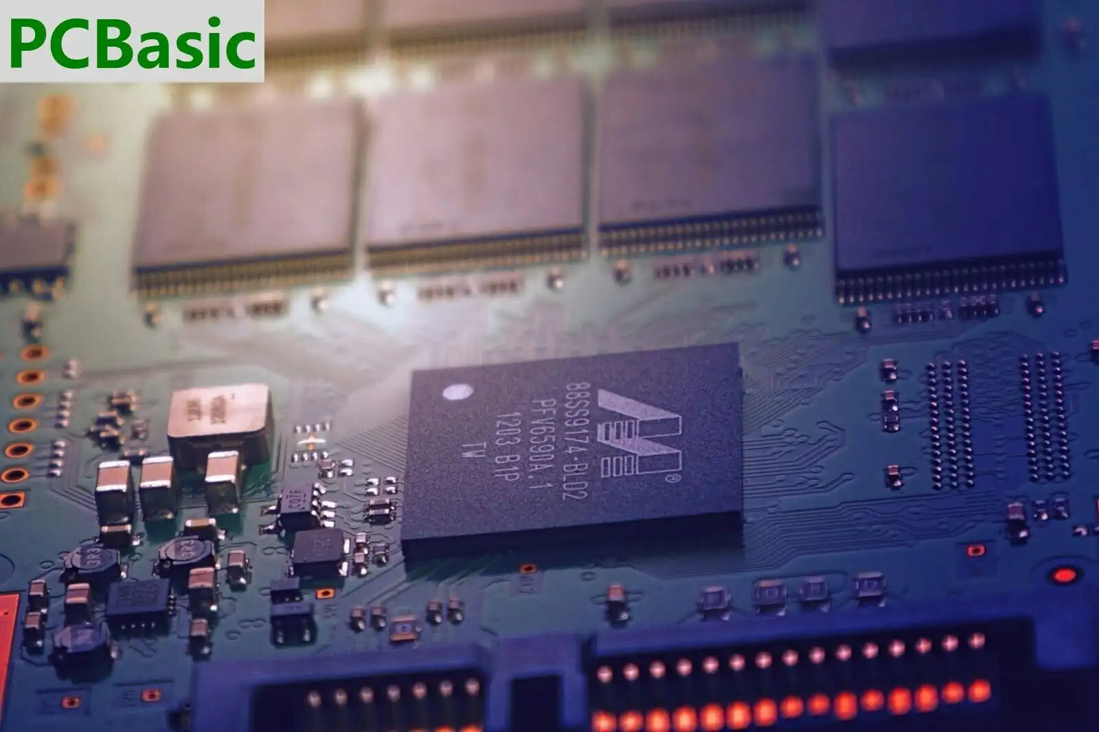
A PCBA is a printed circuit board with all necessary electronic parts around it, making the board a functional electronics circuit ready to be used in its final product. Simply put, you may think of PCBA as a properly functional PCB that can be directly assembled on electronic gadgets to make them work.
To better address the issues and confirm that everything is in place, it would be crucial for designers, engineers, and manufacturers to understand the transition from PCBA to PCB.
 About PCBasic
Time is money in your projects – and PCBasic gets it. PCBasic is a PCB assembly company that delivers fast, flawless results every time. Our comprehensive PCB assembly services include expert engineering support at every step, ensuring top quality in every board. As a leading PCB assembly manufacturer, we provide a one-stop solution that streamlines your supply chain. Partner with our advanced PCB prototype factory for quick turnarounds and superior results you can trust.
The process of PCBA manufacturing involves the placement of electronic components on the board to ensure their proper functionality and operation. The assembly of PCB components are:
1. Resistors: These components ensure the circuit's safety by resisting overvoltages and currents. These are one of the vital components in the printed board assembly process.
2. Capacitors: Capacitors stabilize voltages, storing and releasing volts as needed. They also reduce the noise in an electronic circuit.
3. Diodes: To make sure the current is single-channeled, we use a diode. It protects the circuit from reverse current.
4. Transistors: These are the semiconductor devices that can switch and amplify electrical signals.
5. Integrated Circuits (ICs): ICs are the most intricate circuits that can perform various tasks. We can construct small circuits with the help of these ICs.
6. Connectors: Connectors connect different circuit components that allow power and signal transmission.

Manufacturing approaches for the PCBA are:
1. Put on Solder Paste: The PCB has to be covered in solder paste first. This paste is a mix of flux and powdered solder that covers the sites where components will be attached.
2. Component Placement: The electronic components are placed on the board after the solder paste is applied to it.
3. Reflow soldering: In this, the board is put through a reflow oven after placing all the components. This results in paste melts and solid soldered components on the PCB.
4. Inspection and Testing: Once the PCBA is soldered, it runs through a detailed inspection and testing.
5. Through-Hole Technology (THT): The components with leads that pass through the PCB are called Through-hole Components. These components are then soldered using wave soldering or selective solder techniques.
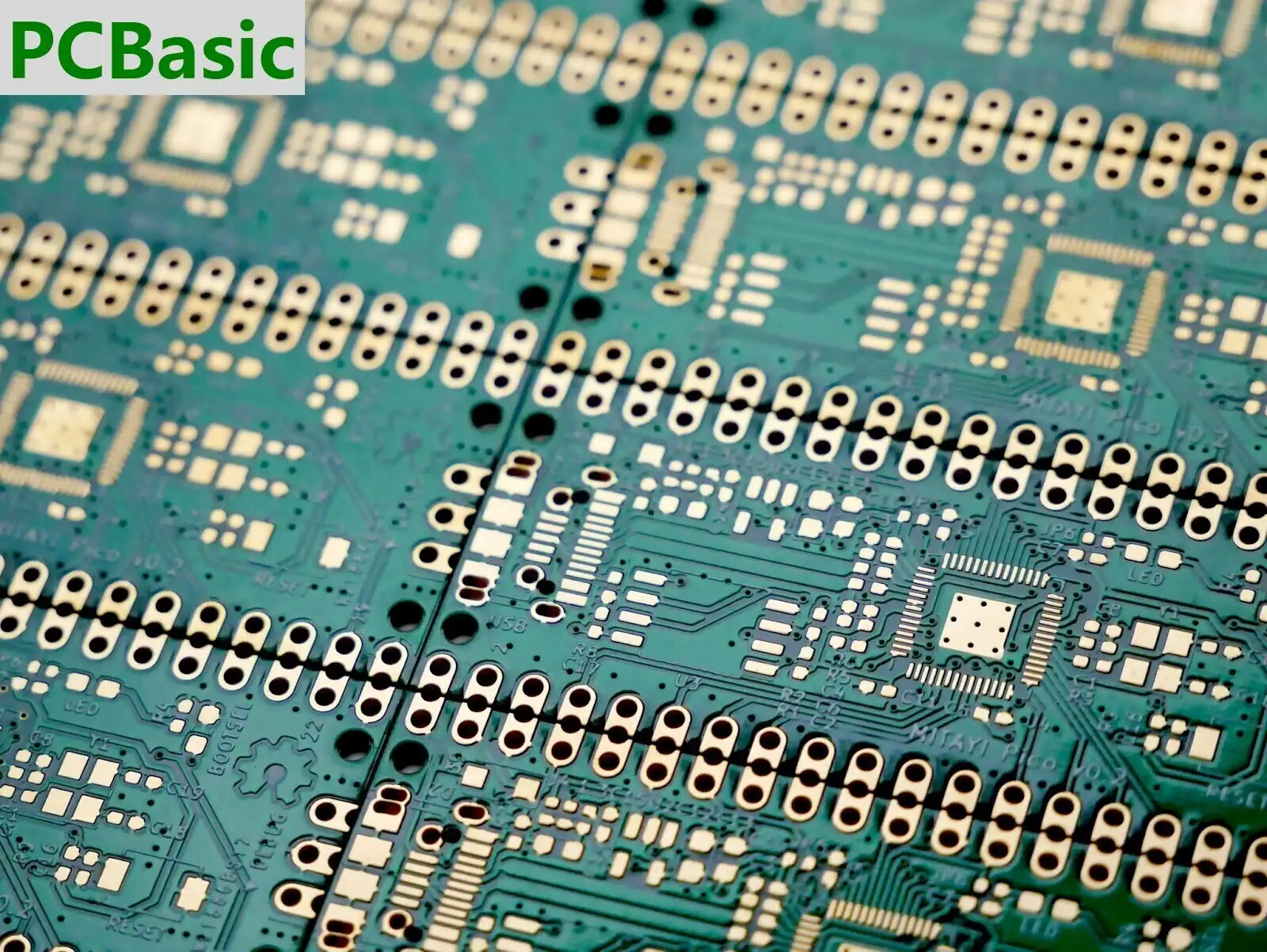
A printed circuit board, or a PCB, is a flat board that provides pathways for electrical current to flow through and connect with electronic components. So, one side of this board is insulated from electricity where electronic components are mounted. The other side of this board is laminated with copper, which makes it conductive. After the design is applied to the board, the unwanted copper is removed through etching, leaving only copper traces that will be used as wires to flow current to components.
Here are six types of PCB:
1. Single-Sided PCB: The single-layer copper traces PCB is the simplest and most commonly used and has a lower cost.
2. Double-Sided PCB: This type of PCB has copper traces on both sides, which allows for more complex circuits.
3. Multi-Layer PCB: Multi-layer PCBs are high-performance for complex circuits. It consists of multiple layers of copper traces, which are separated by insulating layers.
4. Rigid PCB: These types of PCBs are made from solid, inflexible materials and are mostly used where durability is needed.
5. Flexible PCB: For space-constrained areas, this kind of PCB came into work. They are made of flexible materials.
6. Rigid-Flex PCB: This is the mix of both rigid and flexible PCBs that offers both benefits and is used in complex devices.
The design phase of a PCB is a crucial stage in the manufacturing process. It consists of designing the layout of the board and its electrical connections, which involves CAD software to create accurate layouts. PCB design is creating the schematic and PCB layout, making it manufacturing-ready. Every step itself demands levels of accuracy, as slight design flaws could significantly impact performance.

The composition of PCB vs PCBA is primarily this: PCB is made out of a fiberglass laminate, copper patterns, a solder stop, and printing, whereas PCBA contains a PCB, electronic parts, soldering, and potting. If we talk about functionality, a PCB includes electrical interconnections and an electrical-mechanical structure. On the other hand, a PCBA is a working electronic circuitry.
So, the PCB design includes the placement of tracks by the use of CAD software, where features such as trace routing, layer stack up, and signal integrity are emphasized, schematic designs are used for connectivity, and component placement and routing are done in PCBA design. The process of creating a PCB involves photolithographic copper patterning and etching. The PCBA process consists of mounting the components onto the PCB either through holes or on its surface.
During continuity tests, the test subject is either a bare board or a completed assembly. Bare board tests usually include continuity, shorts, opens, and impedance. However, assembled boards include ICT, burn-in, and functional tests.
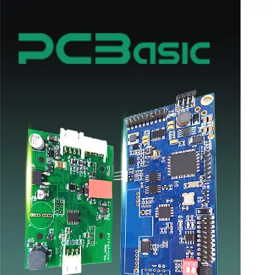
The difference between PCB and PCBA can be learned from the fact that a PCB alone means a blank and empty circuit board, while PCBA means a PCB board that has all the requisite circuitry to function as intended. A PCBA is synonymous with a complete and functional board, while a PCB is not a functioning device since it does not contain essential components. A PCBA is constructed on top of an existing PCB. PCBs and PCBAs are two distinct components of the same process.
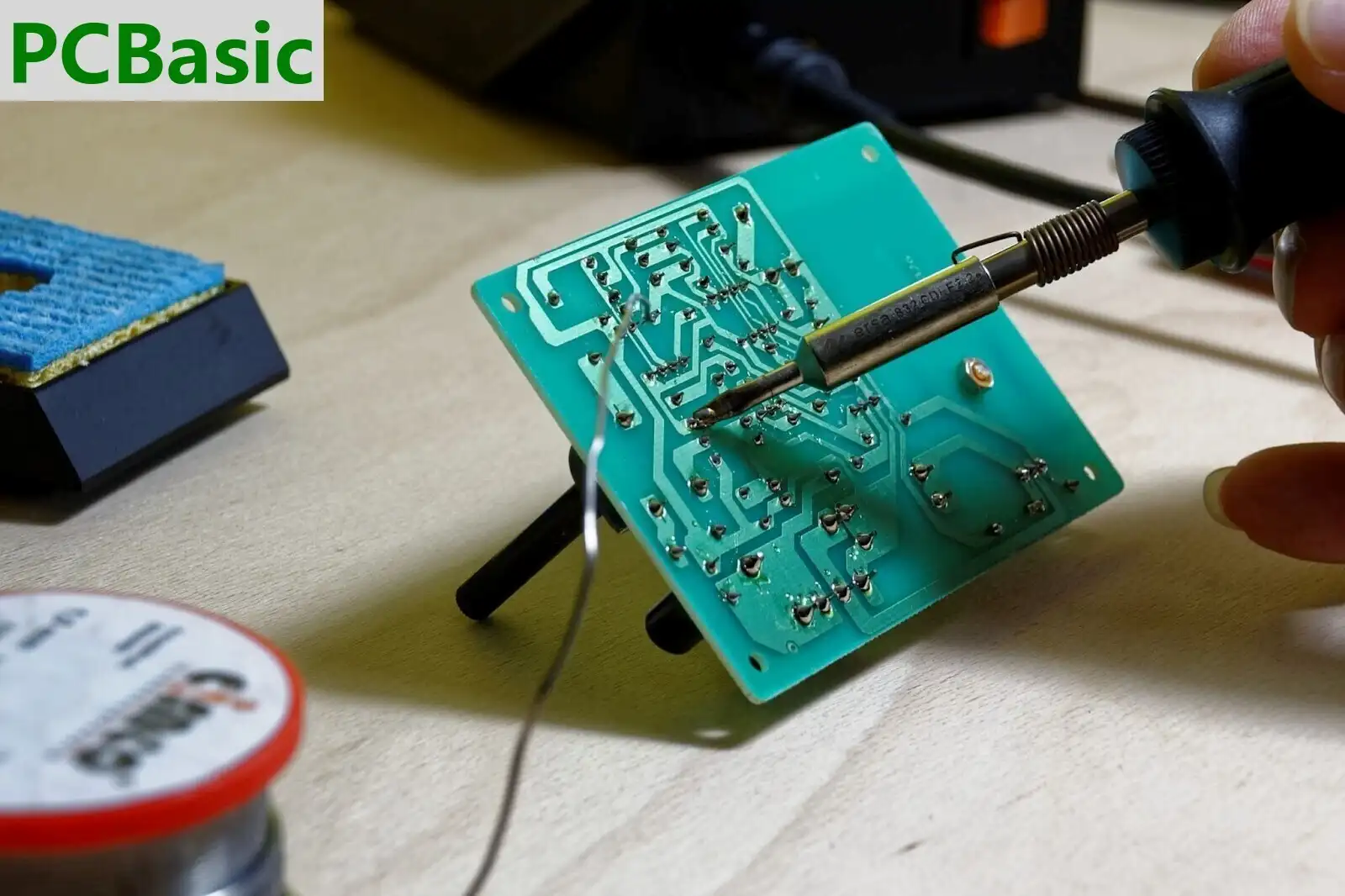
Component leads are inserted into drilled holes in a bare PCB by a process called hole mounting.
In the 1980s, Surface Mount Technology (SMT), which replaced through-hole technology (THI), became widely used in the industry. The reason was its cost-effectiveness and efficiency benefits compared to the method.
Surface Mount Technology (SMT) is the process of physically attaching electrical components to a printed circuit board's surface. SMT has been used extensively in the production of almost all electrical devices since it first gained popularity in the 1980s.
The PCB assembly starts with applying solder paste on the board. Then, with the help of a pick-and-place machine, components are mounted on the surface of the board. Reflow soldering strengthens the connections made after components are positioned and quality control checks are performed. Then, through-hole component inserts are made using manual or wave soldering. Then, the procedure is finished with some functional tests and cleaning. After that, the board is finally ready for packaging and shipping.
What makes PCBA, which stands for Printed Circuit Board Assembly, different from a PCB is that it has all the required electronic components soldered to make it a functional circuit. A PCBA is a finished and functional product used in electronic devices. On the other hand, PCB is just a basic structure that consists of paths for electrical connections and holes to adjust the components. The person in charge, like an engineer or designer, must know this transformation from PCB to PCBA since he has to confirm whether the components are in the correct position and the overall circuit works the way it is designed.

Assembly Enquiry
Instant Quote