Accurate
SMD LED polarity is the most crucial factor in PCB manufacturing and assembly.
Correct SMD LED polarity can be determined to facilitate the expected function
of the specific component and eliminate failure during its usage. This is
because an incorrect polarity may lead to circuit interrupts or total system
interrupts. Therefore, there is nothing as important as the polarity indicators
and signs.
A study
showed that 35% of the total damage to PCB elements can result from incorrect
connections. It has been found that this is responsible for time-related
delays, increased cost, and in some cases, a substandard end product. In the
electronics sector, there is an excellent example of this problem where
different polarity alignments lead to system efficiency losses as well as more
rework.
This
article will provide a framework for learning about the SMD LED polarity,
mount, marks, tests, and symbols with examples. When you finish reading it,
there should be no doubt in your mind about how to approach the LED polarity or
areas to avoid when using PCB. This information is highly beneficial in
preventing manufacturers' problems and maintaining the quality
of the product at any time.
 About PCBasic
Time is money in your projects – and PCBasic gets it. PCBasic is a PCB assembly company that delivers fast, flawless results every time. Our comprehensive PCB assembly services include expert engineering support at every step, ensuring top quality in every board. As a leading PCB assembly manufacturer, we provide a one-stop solution that streamlines your supply chain. Partner with our advanced PCB prototype factory for quick turnarounds and superior results you can trust.
What is SMD LED
Polarity?
Recurrent
in electronics, polarity refers to the qualitative identification of the
direction of current in any constituent part. One needs to take into
consideration that simple items like LEDs, diode or capacitors have anode and
cathode. Polarity should be carried out correctly since it may lead to circuit
breakdown.
SMD LED
polarity determines the direction of the current flow. Usually, the cathode of
the LED is indicated by the use of dots or a flattened end of the metal lead.
Understanding these polarity markings is essential for assembly procedures.
Accurate
SMD diode polarity minimizes damage to the component and achieves a failure
rate reduction of up to 35%. Diode polarity marking on the PCB reduces cases of
wrong placements, leading to enhanced production quality on the PCB diodes.
How to Identify SMD
LED Polarity?
To
identify SMD LED polarity, one first needs to know what anode and cathode are.
1. What is an Anode?
An
anode is the positive electrode of an LED. Through it, current can enter into
the LED from the power source to make the device glow.
2. What is a Cathode?
The
cathode is the negative terminal of the LED, through which current is
outflowing when exiting through the anode. The step is to determine which of
the leads is cathode since putting the LED in the wrong polarity will damage
it.
Some
Approaches:
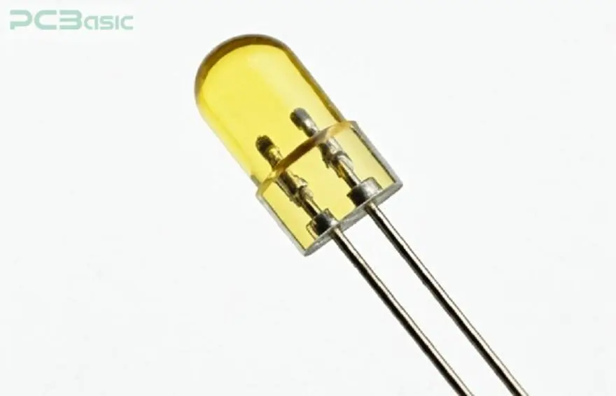
1. Length of the Leads: A convention is
that the anode is always the positive electrode, which is the more extended
terminal; the cathode is the negative electrode, the shorter terminal.
2. Notch or Flat Edge Markings: As most of
SMD LEDs come in packages with no distinguishable flat on the cathode side,
polarity is often marked with a flat edge.
3. Multimeter Testing for Polarity: Polarity can be tested using a multimeter – when the positive probe of the
multimeter is connected to the anode, the LED should turn on.
4. Schematic Symbol Clarification: In the symbolic diagrams, the arrow pointing out of the symbol
shows the direction of the cathode.
These
methods help in assessing the SMD LED polarity correctly to avoid some
disastrous errors on PCBs. Another point would be that an LED polarity's
orientation needs to be stated so that there are no mistakes on the assembly
line.

SMD LED Polarity
Marking on PCB
SMD LED
polarity marking on the PCB is crucial since it guides users on the proper
manner of device installation. In some cases, one can distinguish a dot, notch,
or flat plane on the body of the LED, and this points towards the cathode. Such
visual instructions are essential, especially for technicians who use the
product. This makes it easy for them to elaborate on how they can relate to
anode and cathode. Hence, it avoids problems that arise from wrong polarity on
some of the components used.
Aside
from evident stamps, diode polarity marking on the PCB should also be labeled
so that polarity is evident with the positive and negative poles. It can be
used as standard symbols for the identification of such terminals. Failure to
appreciate and abide by such markings poses a significant risk to achieving
efficient utilization of PCB assembly. It can also help in improving the reliability as well as
performance of the final product.
Consequences of
Incorrect LED Polarity
Many
operational and hardware-related issues can arise if LED pairing is not
conducted correctly.
1. No Illumination or Dimming: The
immediate consequence of wrong SMD LED polarity is that the LED either does not
emit light or only has a low brightness. The disruption of flow is caused by
LEDs being built in a certain current direction. This confuses the design of
the LED if you swap the anode and cathode. Also, the LED can indicate flicker
or work irregularly depending on certain conditions; therefore, the performance
is unpredictable.
2. Potential Component Damage: Satisfactory connections of polarity enhance LED efficiency and lead
to less damage to the parts of the PCB. If it is maintained continuously, the
problem of reverse voltage causes thermal stress to arise. This can lead to the
LED being burnt out or the circuits being damaged. Under severe circumstances,
this leads to short circuits, while in electronic assembly, it translates to a
wider failure.
Thus,
SMD LED polarity is critical as the efficiency of electronic devices depends on
this polarity.

Practical Methods for
Ensuring Correct Polarity in SMD LEDs
The SMD
LED polarity must be correct when assembling to avoid some problems affecting
functionality. Here are some concise methods:
LED
Orientation and Placement on PCBs:
Make sure that the anode is correctly
situated regarding the second terminal- the cathode whose own symbol is placed
on the PCB. In this way, mistakes can be avoided and there is uniformity in
terms of the placement of the facilities, through using placement guides.
Avoiding
Common Mistakes in SMD LED Assembly:
1. Flat Edge and Notch Misinterpretation: You
should be able to read the flat edge or notch on the LED properly to get the
polarity connections right.
2. Cross-referencing Schematic Symbol: Before soldering, check the schematic symbols for the SMD LEDs to define the
anode and the cathode ends.
3. Importance of Clear Markings
on PCB Layout: Make proper use of clear
polarization markings on the PCB to point towards the correct LED polarity.
Preventing the installation of mismatched devices also helps standardize such
terms to avoid confusion.
These
methods help to reduce many problems associated with polarity. Consequently, it
increases the reliability of products in general.
Other SMD Component
Polarity
Knowledge
about the polarity is a crucial requirement for SMD LEDs. It is also crucial
for diode direction marking and SMD components such as SMD diode polarity and
SMD capacitors polarity. It is very important to understand the polarity of the
SMD diode and the SMD capacitor since improper connection of them is fatal to
all devices.
SMD Diode Polarity
SMD
diodes control current and its direction, thus polarity identification is
critical.
1. How do you Determine the SMD Diode Polarity?
It has
a band on the SMD diode that points to the cathode.
2. SMD Diode Identification of Polarity on PCB
Diode polarity
marking on PCB typically has a symbol or a flat line which is used to point at
the cathode. Careful markings help to install circuits correctly, thus
increasing reliability.
SMD Capacitor
Polarity

The capacitors also call for specific
polarity to have the best performance as needed.
1. How to Identify SMD
Capacitor Polarity?
The capacitors also call for specific polarity to have the best performance as
needed. For SMD capacitor polarity, check for a
stripe or flat bar on it. This bar reflects polarity and in case there is no
stripe present; use a multimeter to confirm polarity.
2. SMD Capacitor polarity
symbol on printed circuit board
Identification of the negative terminal is
crucial. The capacitor polarity symbol on the PCB prevents wrong polarity
connections.
Cost reduction and improved device
reliability can be achieved by observing standard diode polarity marking on PCB
and capacitor polarity symbols on PCB.
Conclusion
The life and the efficiency of the
electronic devices depend upon SMD LED Polarity. Thus, it is an important
parameter to take into consideration. Many problems could arise due to a faulty
LED polarity, i.e., lighting dysfunction, damage to the components of the
electronic devices, and assembly problems. There are various measures that
manufacturers can take with an aim of avoiding polarity problems. These methods
include multimeter testing as well as looking at the orientation symbol of
capacitors on PCBs. In other words, the correct polarity marking aids the
developers in gaining quick and easy assembly, hence getting devices that are
more effective for use and have long service delivery.