In
high-speed PCB designs, transmission lines are core structures that must ensure
signal integrity is maintained. Most errors on the transmission line in
electronic circuits propagate through interaction, loss, and distortion, which
occur through interference from today's fast-moving digital and communication
systems. Among the most common types of transmission lines in PCB designs are
two defining types: stripline and microstrip.
But
precisely what are stripline and microstrip, and how do they affect PCB
performance? This article will examine these two transmission lines, break down
their structures, working principles, and certain advantages, and find a
definitive conclusion by the end as to when to use microstrip rather than
stripline for optimum signal performance and better manufacturing efficiency.
What is Stripline?
It is
one of the convenient transmission lines on a PCB, which can carry
high-frequency signals without interference. The last part of the word is more
of an ordinary word since it is nothing but the path for buried electrical
signals in the PCB layers. This makes it preferable in multilayer boards where
the integrity of the signal is an extreme aspect.
It is
commonly used in applications where circuits are high-speed, and communication
systems are used. Due to its characteristic feature along with shielding, the
stripline allows support to very complex signals without loss or interference.
For this reason, it has found a broad application within sectors requiring
precision and stability.
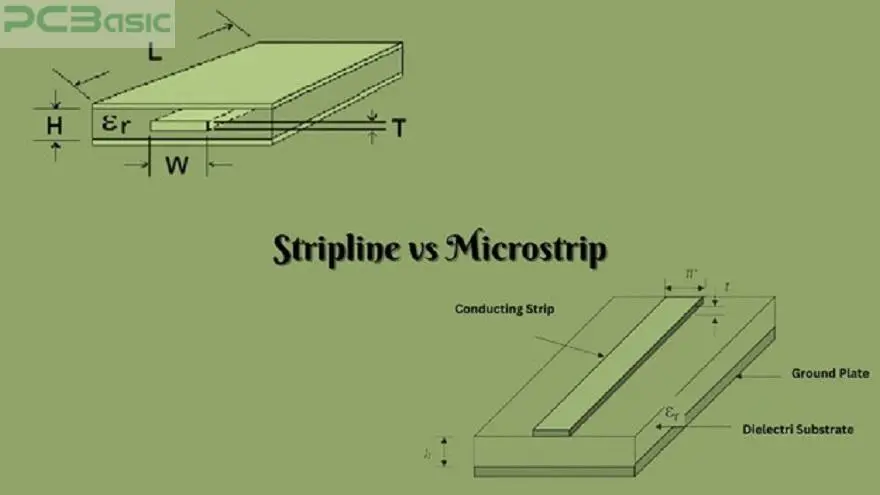
Structure of
Stripline:
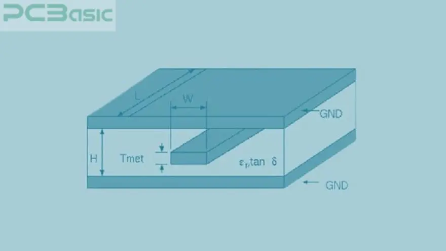
The
stripline configuration is simple but highly efficient. Two layers are formed
by the conductor and covered with dielectric. Between the two layers, there
exist two ground planes; one sits above the structure and the other at the
bottom. These are the ground planes. They act as shields so that outer noises
do not manage to strike the signal. It makes the signal travel quite fast
across the board without interference from outside noises.
Working Principle of
Stripline:
Signals
carried by stripline are contained in a fully shielded environment. The ground
planes shield the conductor; therefore, it has minimal interference with other
components. In this configuration, impedance is constant and essential for
signal integrity. Signal integrity is maintained with stable signal conditions
at high frequencies.
Advantages of
Stripline:
1. Shielding against Other Interferers: The
best advantage of a stripline is its excellent shielding. Since the conductor
is fully enclosed, maximum protection is provided from electromagnetic
interference. Any circuit running at high speed needs immunity against
interference to high levels since minor interference can affect the circuit's
performance.
2. Balanced Impedance: As it is a sandwich construction from inner to inner, the
stripline will likely have a balanced impedance. This means the signal should
be fully un-perturbed while being transmitted along the PCB with the minimum
possibility of distortion or signal loss.
Disadvantages of
Stripline:
1. Complexity in fabrication: The
microstrip would be the most complex to fabricate compared to the stripline. An
increased number of layers, along with the presence of a conductor close to the
ground plane, increases complexity and, therefore, leads to an increase in
cost.
2. Planar Constraints: Because the stripline is striated, it is more bulky on a PCB than,
for example, a coaxial cable. This, in turn, would tend to make boards thicker
overall on average, which may become a problem in compactness-driven designs.
What is Microstrip?
The
microstrip transmission line has been widely used in PCBs because of its simple
and efficient high-frequency design. Unlike the stripline, a microstrip lies on
the surface of the PCB and hence easy to make and deploy. Further, it is widely
used in RF circuits and microwave devices as its design is simple and
economical.
It
involves low-cost design, less space, and is easy to produce; it is therefore
widely used. It carries a high-frequency signal and is very popular in
communication systems, radar, and high-speed electronics.
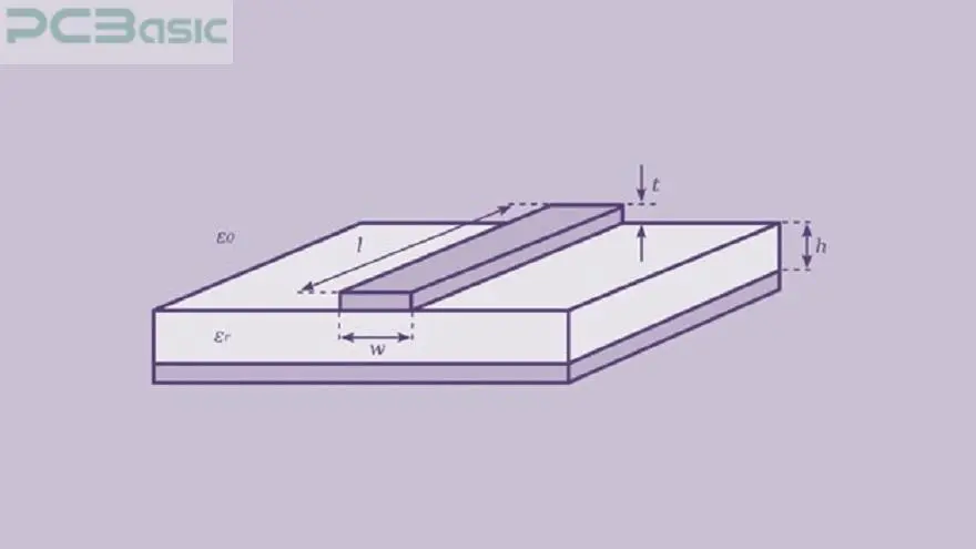
Configuration
of Microstrip:
This is
much less complex in its layout than stripline. In microstrip, one conductor is
placed on a dielectric surface layer while touching the ground plane below only
with one of its sides. The microstrip has an open configuration wherein the top
side of the conductor is exposed to air, unlike every other transmission line.
This inverted ground plane does steer the signal but increases exposure to this
side, which gives the signal far less shielding from possible external noises.
Working Principle of
Microstrip:
In the
case of the microstrip, the signal travels along the upper surface of the
conductor. Due to the presence of one ground plane only at the bottom, the
electromagnetic fields surrounding the conductor are open to interference from
the outer environment. The signal enters the air through partial dimensions and
thus has some exposure to interference sources. However, with high-frequency
operation and low costs, the simplicity makes such a design possible.
Advantages of
Microstrip:
1. Economical: Stock of all raw materials
and layers is saved so that the cost of production comes down.
2. Available for Manufacturing: Because there are fewer layers needed, microstrip is less
complicated and more accessible to manufacture compared with stripline.
Shortcomings of
Microstrip:
1. Highly Susceptible to Interference:
Microstrip is highly susceptible to interference from the outside since it has
almost negligible resistance.
2. Poor balance: This cable needs to be appropriately shielded. So, impedance is
not constant. Hence, the quality of this signal is going to reduce.
Microstrip line vs Stripline: A Comparative Analysis
|
Aspect
|
Stripline
|
Microstrip
|
|
Structural Variation
|
The super
shielding impedance is guaranteed because the shielding is provided by
putting two ground planes sandwiched between stripline sandwiched by two
layers of dielectric material on both sides.
|
A microstrip is
mounted above the dielectric layer but only contacts one side of the ground
plane. Thus, it has a far simpler design but is more susceptible to
interference.
|
|
Operating Principal Comparison
|
Such is a
stripline design: the signals are enclosed and hence protected from outer
sources of interference. Valid primarily for high-frequency use.
|
Microstrip
signals run along the surface. Partial shielding decreases its resistance to
interference, so its performance will be affected in sensitive environments.
|
|
Characteristic Impedance
|
While stripline
and microstrip are of definite impedance, the stripline configuration, being
balanced, gives uniform results.
|
Microstrip
impedance varies. The microstrip cannot control the impedance at high
frequencies. Therefore, CPW coplanar waveguides are combined with it.
|
|
Losses in Transmission
|
The stripline
configuration is the best at reducing loss compared to the microstrip
configuration.
|
Because the CPW
coplanar waveguides reduce loss in a signal, they confine electromagnetic
fields better than traditional microstrip.
|
|
Efficiency and Signal Integrity
|
Stripline
provides excellent signal integrity up to reasonably complex multilayer
designs.
|
Coplanar
transmission lines are an intermediate solution that improves signal
integrity without the complication of stripline.
|
|
Application Usage Scenarios
|
Stripline is
applied in high-speed digital circuits and multilayer PCBs to minimize noise
so that signal integrity may be ensured.
|
Microstrip is
even more prone to interference. Microstrip is mainly used where the ease of
design and cost become more critical in RF designs, wireless systems, and
simpler circuits.
|
Route Differences
Microstrip Routing Techniques
|
Standard Microstrip Routing
|
Surface routing
is sometimes used for simple high-frequency designs.
|
|
Route Differential Pairs
|
Routes the
signals together to reduce noise. It is used in high-speed applications
widely.
|
|
Embedded Microstrip Routing
|
It is
integrated into the PCB with immunity against interference.
|
Stripline Routing
Styles
|
Standard Stripline Routing
|
It is
widespread in multi-layer PCBs wherein the signal must be shielded.
|
|
Coplanar Stripline Routing
|
It introduces
several ground planes for better performance.
|
|
Broadside-Coupled Stripline Routing
|
The space is so
low, but the high-speed signal has to be sent.
|
Design Issues for Stripline and Microstrip
Impedance Control Factors
|
Dielectric Constant (εr)
|
It shows
variations in impedance in dielectric nature even though values for εr are more negligible.
|
|
Practical Dielectric Constant (εeff)
|
This impedance
varies according to the layer structure.
|
|
Trace Width and Thickness
|
A broader and
thicker trace will modify the signal path and, thereby, the impedance.
|
Minimization
Technique Loss
|
For Stripline
|
All these must
be done with the best trace design possible.
|
|
For Microstrip
|
Losses are to
be minimized by proper grounding as well as reduced exposure.
|
Multilayer PCB Design
Considerations
This
would, therefore, require management of signal quality in the stripline and
microstrip of a multi-layered PCB. Quality may be managed through trace widths,
layer stacks, and impedance matching.
Conclusion
There
are two of them: the stripline, better designed and more complex for
fabrication but with greater signal integrity if used as a shield, and the
microstrip, which is more straightforward and much more inexpensive but with
significantly greater susceptibility to interference. This would depend on your
application, cost, and performance.