The new world of electronics makes life more
accessible, and all products are becoming smaller. The products are
increasingly performing the tasks faster and more efficiently. Due to SMD,
which stands for Surface-mounted device, there is a possibility of
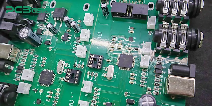
miniaturization of electronics. SMD components are mounted on the surface of printed circuit boards (PCBs), and the process is termed SMT. The SMD component
takes on the role of being the fundamental support of the SMT (Surface-Mount
technology). You can take goods with this newest technology, for instance,
Smartphones, computers, or even industrial products/manufacturing equipment.
This article will tell you about the world
of SMD components, what SMD components are, their importance, typical parts
identification, and how to solder SMD components. At the end of this guide, you
will understand why SMD components are so crucial for the electronics industry
and their impact on the development of devices for everyday use.
What Are SMD
Components?
SMD components are small electronic devices
directly attached to a PCB's surface, unlike traditional components with long
leads that go through holes in the board. There are numerous SMD parts on the
market, including resistors, diodes, transistors, capacitors, and integrated
circuits. Most of them are technically applied in PCB circuits, have their own
features, and play specific roles on the board. And they are soldered on top of
the PCBs through SMT. SMT (surface mount technology) has many advantages, and
many electronic devices are done through SMT in the contemporary world.
 About PCBasic
Time is money in your projects – and PCBasic gets it. PCBasic is a PCB assembly company that delivers fast, flawless results every time. Our comprehensive PCB assembly services include expert engineering support at every step, ensuring top quality in every board. As a leading PCB assembly manufacturer, we provide a one-stop solution that streamlines your supply chain. Partner with our advanced PCB prototype factory for quick turnarounds and superior results you can trust.
Why SMD Components
Are Essential?
As we discussed, electronic devices are
continuously shrinking in size, and SMD components are more powerful and used
in versatile electronic devices. They help to fill this need by soldering more
parts into a smaller board size, having become the core of modern electronics
technology. These devices are not only smaller but also more effective and
reliable.
Advantages of SMD
Components
Here's a detailed analysis of the advantages
of SMD components that will help you understand why SMD components are so
popular.
1. Smaller Size, More
Precision, and Compact Designs
Precision and compact designs in small sizes
are the most significant advantages of SMD components. Through-hole components
with long leads that pass through the PCB need ample space to make a complete
circuit. While SMD parts are significantly smaller in size, they can be
directly mounted onto the PCB without drilling. Hence, more components can be
soldered into the board to make devices more compact and lighter.
This technology can be understood by using
the example of a modern smartphone. You can see inside a highly complex and
unique circuit board full of hundreds or thousands of SMD components. The
smartphone would have to be much larger if prepared with the traditional
large-size components. SMD technology enables these components to fit closely
together to produce slim sizes.
2. Faster and More
Efficient Production
Earlier, all the components were soldered
manually onto the PCB in the construction of the electronic devices, a process
that was quite time-consuming and tiresome. Manufacturing becomes faster with
the use of SMD components. SMD components are placed through machines.
These machines pick the components and place them on the PCB quickly and
accurately. These machines help to make the production process faster and can put
thousands of SMD parts in an hour. There is no need to drill holes in the PCB
to assemble SMD components, reducing production time and costs.
3. Better Performance in High-Frequency
Circuits
SMD components drive better electrical
performance in high-frequency circuits than traditional components. Traditional
components will exploit the extra length of the leads, which introduces
parasitic inductance and capacitance that interferes with operations of
circuits. If leads are required, they should be short or, in some cases,
non-existent, and this is where SMD components are less problematic. Thus,
SMD components are superior, particularly at high speed and high frequency. More efficiency is essential in
modern electronics when the devices are called upon to process large data
within a limited time. So, they are necessary for
today's manufacturing, including smartphones, computers, communication devices,
and others.
4. Cost Savings in
Manufacturing
SMD components can be more expensive than
traditional components, but the savings are much greater in the manufacturing.
Because SMD used less material in the PCB assembly than in the through-hole
process. Large-scale production in industries creates a big cost difference. Manufacturers
benefit from making quality and reliable components in large quantities at a
lower cost and in a short time. Then, SMD components have become the standard
in today's electronics market.
5. Greater Reliability
It has come to the point that SMD components
are being deployed nearly anywhere; why? It's simple – reliability. For
example, resistance is mainly used in portable devices for stress, such as
vibrations or impacts. Besides, there are many elements placed near one
another. Such an arrangement assists in avoiding troubles
and any interferences in such a multitude of tightly compacted circuits.
This reliability is quickly felt when device performance is required over long
intervals, such as in the medical sector, car assembly industries, and
manufacturing industries.

A Comprehensive
Guide to SMD Components
We've described the benefits of SMD
components above. This section will further detail the different kinds of SMD
components in the market, how to identify or differentiate them, and how to compare them according to packages.
Types of SMD
Components
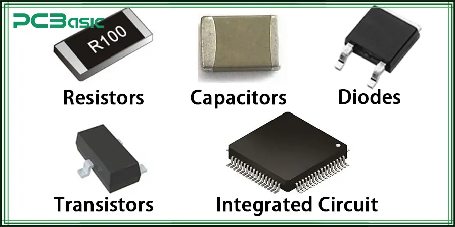
SMD components have different types, each
performing a specific function in an electronic circuit. Here are the most
common types you will find:
• Resistors: This type of component helps to control the voltage of electricity in a circuit
and the flow of electrical current. They come in various resistances based on
the needs and size of the given circuit.
• Capacitors: Capacitors are organized to hold and provide electrical energy. They are
applied in the process of soldering PCB for filtering, supply power, and signal
conversion.
• Diodes: Diodes are used for protection, rectification of AC to DC, and signal modulation
circuits. Diodes allow current flow only in one particular direction. In this
respect, they can be classified into various kinds based on power. Diodes
are used in power supplies, signal demodulating circuits, LED lighting, etc.
• Transistors: Transistors are semiconductor devices that are mainly used for amplification
and switching. They are used in all types of circuits, ranging from simple
circuits to highly integrated systems. SMD transistors are more efficient and
smaller.
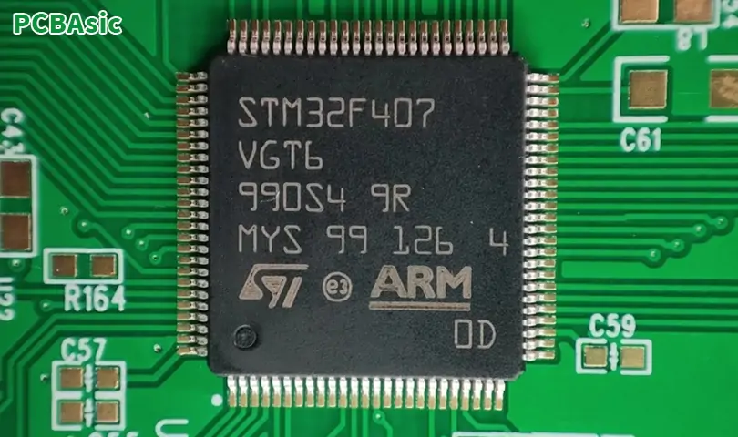
• Integrated
Circuits (ICs): ICs might be the most complex SMD components, which contain
millions of transistors, resistors, capacitors, and other components within a
piece. They are incorporated within Microcontrollers to Processors and memory
chips and also exist in separate Voltage Regulators.
Each of these components plays a crucial role in
the overall function of an electronic device. Understanding them is important
for someone working in electronics design or repair business.
SMD Components
Identification Chart
Identifying SMD components can be difficult due to their small size
and the limited stock available for markings. However, understanding them is
very important for proper assembly and troubleshooting.
Here is a SMD components identification
chart:
|
Components Type
|
Package Type
|
Code/Marking
|
Description
|
Example
|
|
Resistors
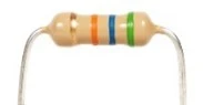
|
0603,0805,1206
|
3
or 4 digits
|
Numeric
code indicating resistance value in ohms (e.g., 103 = 10kΩ)
|
0805:
103 (10kΩ)
|
|
Capacitors
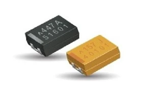
|
0603,0805,1206
|
Usually
none
|
Often
identified by color: brown/black for ceramic, yellow/orange for
tantalum
|
0805:
Brown (ceramic)
|
|
Diodes
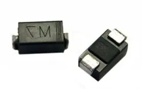
|
SOD-123,
SOD-323, SOT-23
|
Line/Bar
marking
|
The
line or bar denotes the cathode (negative) end
|
SOD-123:
Line marking
|
|
Transistors
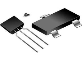
|
SOT-23, SOT-223
|
Alphanumeric
code
|
Code
often starts with a letter followed by numbers indicating transistor type
|
SOT-23:
M6 (NPN)
|
|
Integrated Circuits (ICs)
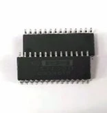
|
SOIC,
QFP, BGA
|
Part
number
|
A
part number indicating the IC's function and specs
|
SOIC:
74HC00 (NAND gate)
|
|
Inductors
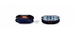
|
0603,
0805, 1206
|
Alphanumeric
code
|
Code
indicating inductance value (e.g., 100 = 10µH)
|
0805:
100 (10µH)
|
|
LEDs
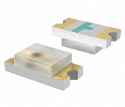
|
PLCC,
0805, 1206
|
Color
indication
|
Often
identified by package color, different colors indicate different wavelengths.
|
PLCC:
Green
|
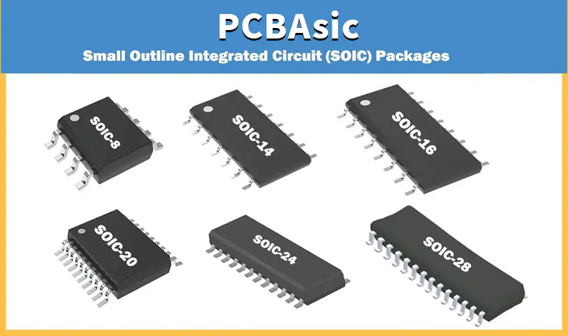
SMD Package Types
The term SMD package deals with the size and
form of an SMD component. The package type is quite significant because it
defines how the component will be fitted into the PCB and how it interacts with
other components.
Here are some common SMD package types:
SOIC (Small
Outline Integrated Circuit): This package is
commonly used in integrated circuits and has a rectangular shape with leads or
pins on the sides. The SOIC package comes in several width/pin combinations.
QFP (Quad
Flat Package): QFPs have leads on all four sides
and are used for those ICs that need large connections. They are incorporated
into microcontrollers and processors.
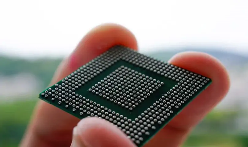
BGA (Ball
Grid Array): BGA packages are applied high-density
and functional ICs such as processors. They have a grid of solder balls on one
side of this chip carrier. These solder balls are used to connect this chip to
the PCB.
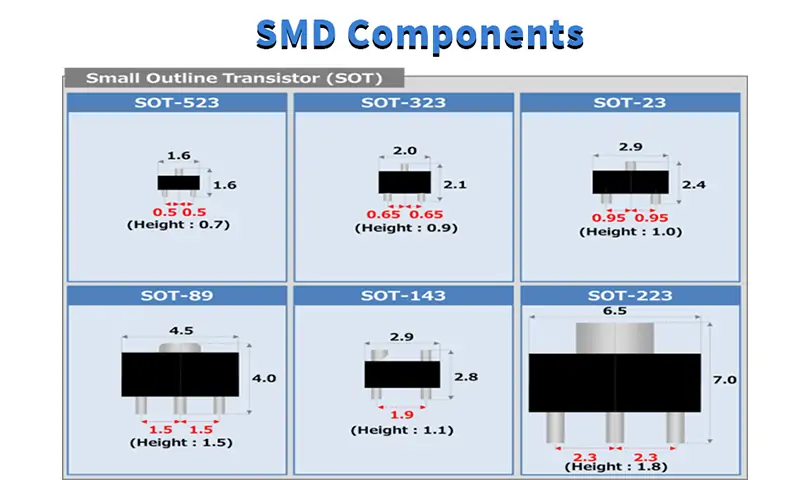
SOT (Small
Outline Transistor): SOTs are primarily employed to
define the region of transistors and mutually similar elements. SOTs come in
various sizes and shapes and may accept three or more leads. They are usually
used in power control circuits.
Each package is used for a specific purpose,
and the choice of the package depends on the specific requirements of the
circuit design.
How to Check SMD
Components?
Check is a very important aspect of
manufacturing and repairing the components. Some faulty parts will cause the
device to be non-functional. You can check SMD parts through the following
procedures:
Visual Inspection
Visual inspection is the initial stage of
examining SMD components. It is used to check for any visible signs such as
cracks, fading, or any part that is missing. Large parts can be done with the
naked eye without any microscope, but you will need hand lenses or microscopes
to inspect small parts.
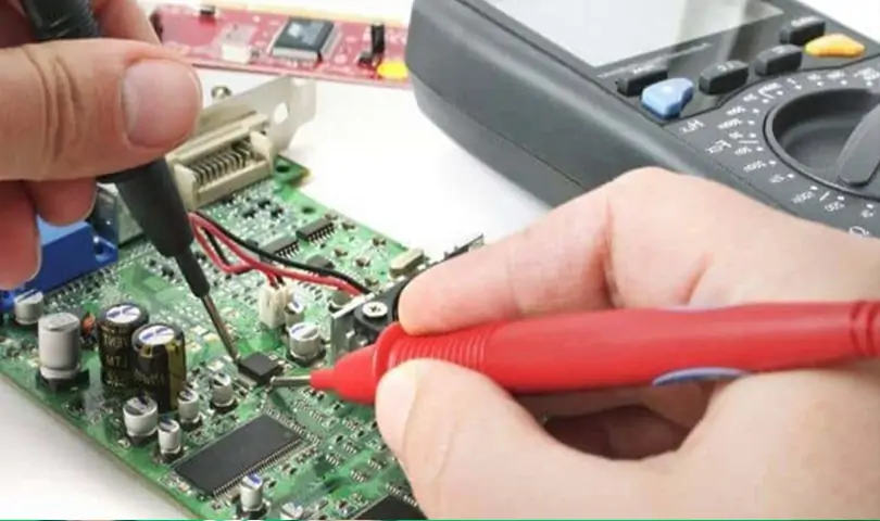
Using a Multimeter
A multimeter is a tool by which resistance,
capacitance, and continuity tests upon SMD may be carried out on SMD. Depending
on the type of SMD components, the method of using a multimeter can be
different for each type.
Here's how you can use a multimeter for
different types of components:
• Resistors: Rotate the dial to set the multimeter to ohms and place the two probes by the
two ends of the resistor. Reading is marked on the resistor, which can
vary for different types of resistors.
• Capacitors: When testing capacitors, check the capacitance of the capacitor, which is
written on the capacitor. Place the probes at the two end capacitor terminals
and compare the readout with the capacitance of the capacitor. Small SMD
capacitors cannot checked through this method. Small SMD capacitors require an
auto-ranging digital capacitance meter.
• Diodes: Diodes have two ends named as anode and cathode. The anode is positively
charged, and the cathode is negatively charged. Set the red probe to the anode
side terminal and the black cathode to the cathode side terminal. Note that
voltage (normally from 0. 6V to 0. 7V for a silicon diode) must be indicated in
one direction while there is no indication in the other direction.
Automated Optical
Inspection (AOI)
Automated optical inspection (AOI) is used
for deep inspection at large-scale production. AOI systems are used for PCB
scanning and analysis of any flaw in the components or solder joints with the
help of cameras and sophisticated software. AOI is used at places where the
naked eye cannot find it.
X-Ray Inspection
X-ray inspection is used to examine
internally the connections and solder joints. X-ray machines can scan hidden
features and flaws in the connections. An X-ray can visually disclose internal
features of strength or potential areas of compromise within the components of
a system without interfering with those components.
Functional Testing
Towards the end of all the testing that is
carried out, there can be a requirement for functional checking of the
assembled PCB. This means applying voltage across the circuit and evaluating if
the circuit performs well and the device is functioning as required. These
methods ensure that SMD components function in the right way.

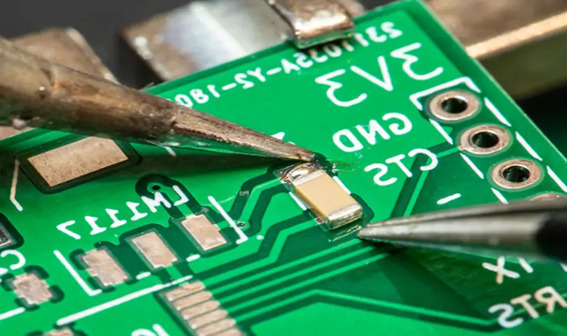
How do you Solder
SMD Components with a Soldering Iron?
Soldering iron for SDM components is quite
an important aspect of this piece. Let's look at how to solder SMD components
with a soldering iron.
Step-by-Step Soldering Process
Soldering SMD components is a delicate
process that is always done with the right tools and instruments. In
large-scale production, numerous automated machines perform soldering. But
usually, soldering is done manually for prototyping, repairs, or small-batch
production.
Here is step by step guide for manual
soldering iron for SMD components:
Step 1: Prepare the PCB
First, take a new PCB and apply solder paste
to the pads. Solder paste helps in ensuring good soldering between the SMDs and
the PCBs. It is a mixture of flux and solder elements.
Step 2: Place the Components
This is how you should correctly place the
SMD parts on the correct place of the PCB board using the tweezers. Ensure all
the components are mounted onto their respective places, and then
interconnectivity can be established appropriately.
Step 3: Solder the Components
Heat the component leads
and the pads with a well-knob soldering iron. The solder paste will melt and
create a strong relationship between the component and the PCB. Temperature
should be limited; a temperature higher than the limit is bad for the
components.
Step 4: Inspect the Solder Joints
Leave it for some minutes until the joints
are cold. Checked the circuit and joints are soldered. A magnifying glass or
microscope will be in your hand at this point.
Step 5: Clean the PCB
The last process is to clean the PCB to
remove the residual flux, which can lead to corrosion of the layer if not
cleaned. Cleaning is usually done with a soft brush together with isopropyl
alcohol. Soldering of SMD components is a little tricky but can be done with
the right tools and techniques.
If you want to mass-produce, the best PCBA
manufacturer in China is PCBasic. You can click here: www.pcbasic.com for more information about PCBasic.
Conclusion
Small surface mount devices are the key to
miniaturization and are fast and efficient electronic devices. Mastering these
skills is important for anyone involved in electronics design, manufacturing,
or repair. You can enhance your knowledge and skills, leading to better designs
and more reliable electronic products.
FAQs
1. What is SMT?
Surface-mounted technology, or SMT,
is a joining technology where the components are placed directly onto the PCB
surface. It is different from through-hole technology. It has become the most
popular technique in the electronics industry as it enables high-density
circuits and automated assembly, which are heavily demanded in today’s electronic devices.
2. What is an SMT Line?
An SMT line is an assembly line intended to
assemble printed circuit boards by installing surface-mounted device
components. Its key stages include:
·Stencil Printer: Depicts the solder paste on the PCB through a stencil.
·Pick-and-place machine: this machine is an automated device used to assemble printed
circuit boards (PCBs). Its primary function is to pick up surface-mount devices
(SMD components) and accurately place them at specified locations on a PCB.
·Reflow Oven: Reflow soldering refers to the process of heating the solder paste
that flows through it, melting it, and then cooling it to create a tighter
connection between the SMD components and the PCB.
·Inspection Systems: Usually, the machine used is AOI. It is to search for defects like
the rotated components or the poor solder connections.
·Rework Station: It is primarily used for repairing and reworking components on
already assembled printed circuit boards (PCBs).
SMT lines provide a quick, precise, and
automated means for manufacturing electronics and appliances that are applied
in communication, automobiles, and industries.
3. SMD VS SMT
SMD, also known as Surface-Mount Device,
refers to tiny components that are mounted on the , such as resistors,
capacitors, diodes, transistors, and integrated circuits.
SMT (Surface-Mount Technology) is a process
or method used to place SMD components on the PCB. In the simplest terminology,
SMD refers to the part, while SMT refers to the process of affixing and
soldering that part on the PCB.