
Global high-mix volume high-speed PCBA manufacturer
9:00 -18:00, Mon. - Fri. (GMT+8)
9:00 -12:00, Sat. (GMT+8)
(Except Chinese public holidays)





HomePage > Blog > Knowledge Base > Smart Lighting PCB Assembly: Driver, Control, and Testing Requirements
1. What Does Smart Lighting PCB Assembly Include?
2. Smart Lighting PCB Assembly Requirements for Driver and Control Electronics
3. Testing Smart Lighting PCB Assembly Beyond Basic Power-On Checks
4. Preparing Smart Lighting PCBA for Volume Production
A smart bulb that
flickers at low brightness levels. A wall dimmer that falls off the network
after being restarted. A panel light whose colors change after only a few weeks
of operation. Such issues can result from design, firmware, thermal, or
assembly problems within the fixture, that is, why smart lighting PCB assembly
needs special attention.
The market gives that attention real weight. According to a 2025 forecast by MarketsandMarkets, the global smart lighting market was estimated to be valued at USD 9.86 billion in 2025, increasing to USD 17.38 billion by 2030 at a 12.0% CAGR. A smart lighting fixture may combine LED driver circuitry, control electronics, and wired or wireless interfaces, all of which need to operate reliably under the specified conditions for years.
In this article, you will learn about the components of smart lighting PCB assembly, requirements set by LED driver and control board electronics, the need for testing beyond just power-on tests, and how to ready your design for mass production.
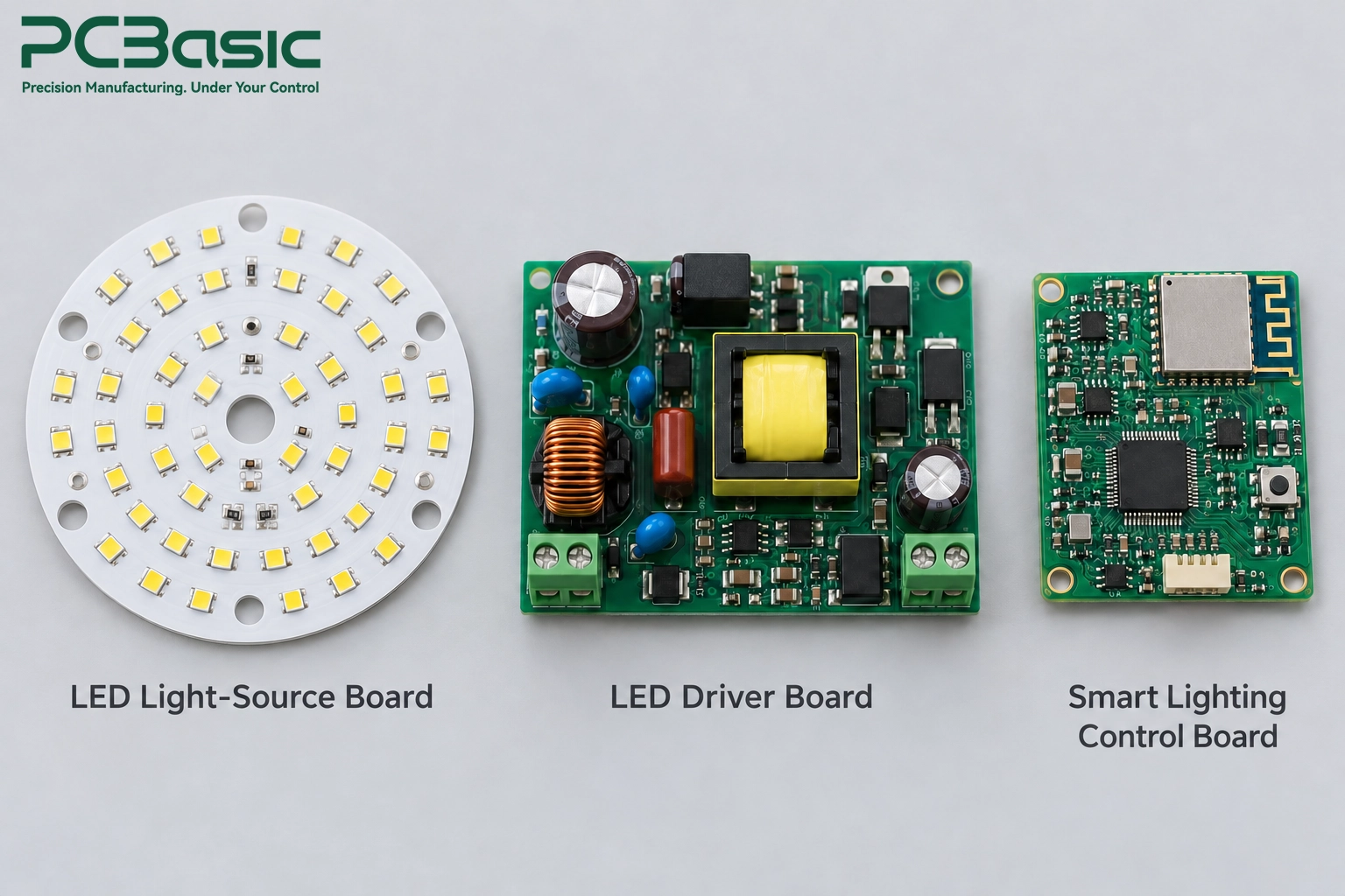
Smart lighting PCB assembly rarely means one board. Depending on the product, a fixture carries a single board or multiple boards, and each type asks something different from the line.
The LED source board is the one where the emitters reside and dissipate the heat. The board may use a metal-core substrate, and component placement accuracy and thermal-pad solder quality contribute to heat transfer, alongside the substrate and the fixture’s thermal design.
The driver board converts mains or DC input power to a regulated LED current. The board contains power MOSFETs, magnetics, and bulk capacitors, therefore LED driver PCB assembly is a power electronics process as much as an SMT process.
The smart lighting control board controls the intelligent functions through a microcontroller, communication circuitry, sensors, and a dimming interface.
The table below summarizes how the three board types differ.
|
Board Type |
Main Function |
Assembly Focus |
|
LED light-source board |
Holds the LEDs and spreads their heat |
Thermal pad soldering, LED placement accuracy, metal-core substrate handling |
|
LED driver board |
Converts input power into stable LED current |
Power components, through-hole magnetics, isolation distances |
|
Smart lighting control board |
Runs firmware, wireless, dimming, and sensing |
Fine-pitch ICs, wireless module placement, RF-sensitive layout |
The product can combine all these functions on one board or distribute them across several boards. Such decisions influence the entire process of the assembly.
The smart lighting control board requires a more detailed examination despite its compact size because the board contains the firmware, the radio, and the sensors, and thus any assembly error may disable the entire smart functionality of the lamp.
Compact light fixtures may incorporate the driver, the controller, and the LEDs into one or two PCBAs to reduce size and cost. But the disadvantage here is that the heat generation, switching noise, and the radio all reside in the same place because of space constraints.
Larger light fixtures may keep these functions on separate boards. The separate smart lighting PCBA enables using one control board for different versions of a fixture and can help separate the radio from switching-noise sources, but requires additional connectors and wiring that also have to be inspected separately.
Neither method works best in all cases – it depends on fixture size, thermal characteristics, and the number of product variations using the platform.
Serviceability and warranty issues are also relevant. If the control board is separate, then a support team may be able to replace or upgrade it without disturbing a driver board, although the modified product may still require verification.
Driver and control electronics sit side by side in a fixture, yet they stress the assembly line in very different ways.

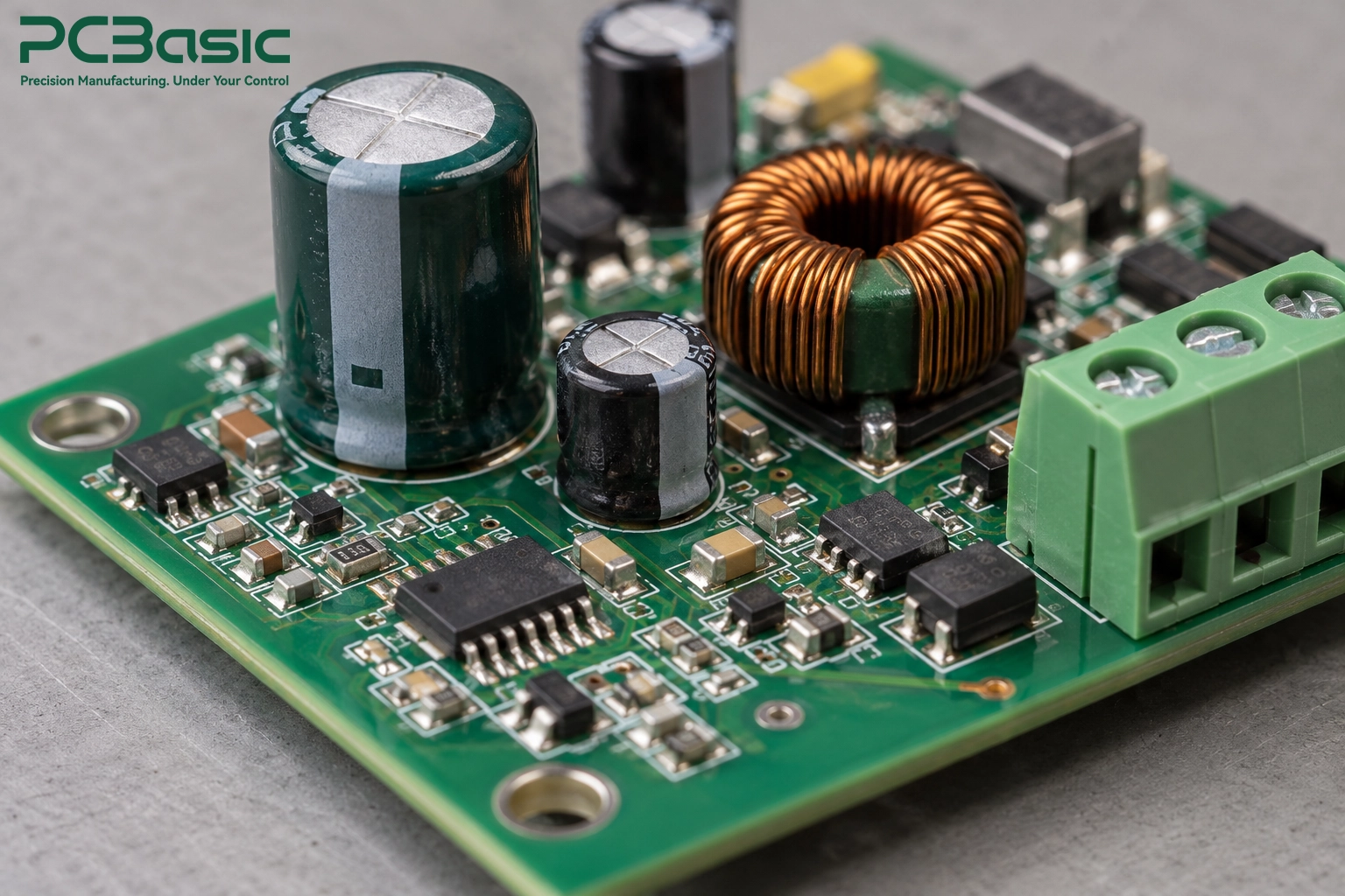
Power MOSFETs, rectifiers, and other components with exposed thermal pads dissipate heat in use, and excessive or poorly located solder voiding can impair heat transfer. Volume of paste, stencil design, and reflow process all determine how well the thermal pad wets.
Significant voiding beneath a driver MOSFET can increase its junction temperature, potentially reducing component life and increasing thermal stress on nearby capacitors.
Another variable to take into account is metal core LED boards. These boards can have different thermal responses from conventional FR-4 boards, so manufacturers must optimize their reflow profiles to prevent cold solder joints and overheating.
PCBasic handles this through SMT assembly, with SPI to check paste before placement and AOI after reflow. For packages with hidden joints, such as bottom-terminated power parts, X-ray inspection adds a closer look where the design calls for it.
The control side is dependent upon fine-pitch ICs, small passives, and a wireless module. The smart controller PCB assembly will need to position all of those components properly while preserving the antenna clearances specified by the module manufacturer.
This becomes an even greater challenge in case of wireless components. The IoT module PCB assembly handle moisture-sensitive modules according to their specified moisture sensitivity levels and control the reflow profile to prevent damage and protect the RF part, since a small change in the process may affect the range without causing any visual defects.
Cleaning is another important consideration. Depending on its chemistry and the operating environment, flux residue near high-impedance sensor inputs can cause leakage, while residue near an antenna may affect RF performance.
Sensors deserve attention as well. For example, an ambient-light or motion sensor can vary its readings because of thermal effects or wrong placement.
Many drivers continue to use through-hole components such as electrolytic capacitors, transformers, terminal blocks, and mains connectors. Through-hole packages may be selected for mechanical retention, component size, current requirements, or the approved electrical design.
Order is important. In most cases, SMT goes first, followed by the through-hole mounting process. Selective soldering involves heating of the specific joints to avoid damaging the neighboring heat-sensitive components. PCBasic supports through-hole insertion and selective soldering as part of mixed-technology assembly.
The incorrect sequence leads to rework. The large connector placed too soon may obstruct soldering-tool or fixture access and prevent the joint from being heated; therefore, the correct sequence should be determined in advance.
A board that lights up on the bench has proved very little. Lighting products fail in quieter ways: a flicker at ten percent brightness, a radio that drops under load, a driver that runs hot after an hour.
Inspection and electrical tests are the initial stages because this helps in finding errors in the process inexpensively. SPI checks solder-paste deposition, AOI checks component placement and visible solder joints, and X-ray inspection examines relevant hidden joints. ICT or flying probe testing can check accessible circuits for shorts, opens, and selected component values.
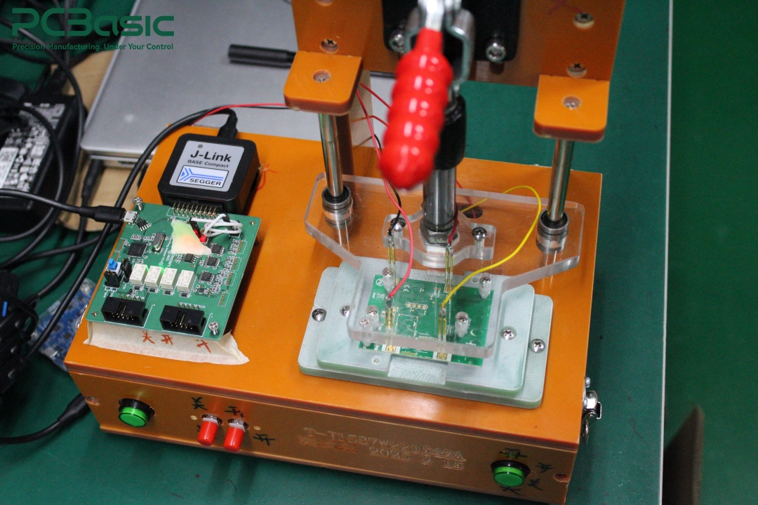
PCBasic offers both ICT and flying probe testing, and their selection depends on volume and availability of test points. The flying probe is best for prototypes and low volumes without a fixture, whereas ICT works out better for higher volumes. Lighting control PCB assembly finds maximum advantage in this layered process, because each stage can identify different faults before they lead to additional processing or rework costs.
Functional testing begins with the fixture. With appropriate optical equipment, the fixture measures the light at multiple dimming levels, checks for flickering issues, and verifies that the color output meets the specified requirements.
This stage uncovers defects unseen by the naked eye. A driver with a borderline component could be fine at full brightness but become unstable or flicker at low dimming levels.
In the case of lighting control PCB assembly, this testing also makes sure that the interface, whether analog, PWM, or digital, is functioning correctly.

The behavior of the wireless system may be different after the switching action starts. It may either lose range or fail to execute commands due to RF interference caused by the switching noise.
Therefore, the testing needs to simulate the actual behavior of the control board. Commands need to be sent through the wireless system to confirm that there is proper communication.
Heat can affect how long the lighting board will last. The temperature rise test measures how hot critical components become under load, while aging tests operate the board for an extended period before shipment.
PCBasic can perform FCT, temperature rise tests, and aging, depending on what the particular project requires. The test scope, test fixture, limitations, and documentation have to be established for the particular project, as bedside lamps and industrial high bay controllers require different types of testing.
A design that builds well at ten units can still struggle at ten thousand. Preparation before the ramp keeps the smart lighting PCBA consistent from the first board to the last.
First, freeze anything that should not vary. This includes the BOM, which is frozen together with the firmware and the configuration, including dimming curves, device-ID assignment rules, and pairing procedures.
The smallest change here could result in behavioral differences in a whole production run. With revision control, everybody has a single common point of reference, and the problem in the field is traced back to a specific build rather than a random one.
Component selection also requires the same level of rigor. An alternative that meets the specification in the datasheet may act in different ways in a dimming circuit.
Agree on the fixture and the pass and fail criteria before the manufacturing process begins; do not wait until the middle of the process to make these decisions. Clearly define in writing the brightness limits, the driver current, power consumption, and radio performance, and then validate the test fixture against those requirements using a known-good sample. The practicality of the fixture is also important, including features such as spring-loaded test probes, clear pass or fail indicators, and fast board insertion.
Clearly defined limits help prevent disputes regarding borderline test results, and they provide the customer with meaningful test results.
A first-article build checks the first boards against the drawings, BOM, firmware, and test limits before the full run starts. Approval at this stage costs far less than rework later.
PCBasic supports the full path, including component sourcing, turnkey assembly, first-article confirmation, and production traceability. Sourcing and turnkey assembly keep the BOM under one control.
Traceability ties each board to its components, process data, and test results, which supports revision control and repeatable delivery from batch to batch.
Smart lighting PCB assembly is achieved when the driver, control electronics, and testing strategy form an integrated system. Reliable soldering for the thermal pad, an undisturbed area around the antenna, and loading testing form barriers against different risks to the product’s reliability.
PCBasic can provide support for your lighting program with SMT and through-hole assembly, inspection, functional testing, and volume production. If your next smart light fixture requires a manufacturing partner who understands both the power side and the smart side, we'd love to talk.
Q1: What is smart lighting PCB assembly?
It is the manufacturing process for the boards inside connected lighting, including LED light-source boards, driver boards, and control boards with wireless modules and sensors.
Q2: Why does LED driver PCB assembly need extra attention?
Driver boards switch real power and carry heat-generating parts, so thermal pad soldering, through-hole components, and the assembly sequence all affect reliability.
Q3: Why isn't a power-on test enough for smart lighting?
A board can light up and still flicker when dimmed, lose wireless range under load, or overheat after an hour, and functional, load, and thermal testing can reveal those faults.
Q4: Should a smart lighting product use one board or several?
Compact bulbs often integrate functions to save space, while larger fixtures separate the driver and control boards to manage heat and switching noise, so the choice depends on size and thermal budget.
Q5: What should be agreed before volume production starts?
The team should lock the BOM, firmware, and configuration, and agree on the test scope, fixture, limits, and records, so every batch follows the same baseline.

Assembly Enquiry
Instant Quote

Phone contact

+86-755-27218592
In addition, we've prepared a Help Center. We recommend checking it before reaching out, as your question and its answer may already be clearly explained there.
Wechat Support

In addition, we've prepared a Help Center. We recommend checking it before reaching out, as your question and its answer may already be clearly explained there.
WhatsApp Support

In addition, we've prepared a Help Center. We recommend checking it before reaching out, as your question and its answer may already be clearly explained there.
