
Global high-mix volume high-speed PCBA manufacturer
9:00 -18:00, Mon. - Fri. (GMT+8)
9:00 -12:00, Sat. (GMT+8)
(Except Chinese public holidays)





HomePage > Blog > Knowledge Base > PIR Motion Sensor PCB Assembly: What to Check Before and After Soldering
1. What to Check on the BOM and Assembly Drawing
2. How the Sensor, Lens, and Enclosure Fit Together
3. Soldering and Inspecting the Sensor Board
4. How to Test the Assembled PIR Sensor Board
A misplaced pin, an unapproved component substitution, sensor placement outside the specified tolerance, or improper cleaning can quickly turn a batch of assembled boards into unreliable stock.
For hardware engineers and procurement managers, maintaining quality relies on clear verification standards at every phase of manufacturing. This guide walks through the essential checkpoints required before and after soldering to help ensure every motion sensor PCBA meets defined performance requirements under specified operating conditions.
Before a single surface-mount component is placed on a bare motion sensor PCB, engineering and procurement teams must conduct a joint review of the Bill of Materials (BOM) and mechanical assembly drawings. Discrepancies at this stage can cause line stoppages and component rework.
In designs that use a discrete PIR sensor and an external signal processor (such as a RE200B pyroelectric sensing element paired with a BISS0001 signal processor IC), distinguishing between sensing elements and processing ICs is critical:
• Discrete vs. Integrated Solutions: Purchasing teams must avoid confusing discrete pyroelectric elements with downstream signal-conditioning ICs. Note that integrated PIR sensors house amplification circuitry directly within the package and require only their complete part number without separate internal BOM items.
• Full Part Numbers and Suffixes: Suffixes may indicate pin assignments, operating voltage ranges, package types, sensitivity grades, or packaging options, depending on the manufacturer. Purchasing incorrect package variations can lead to incompatible footprints on the physical board.
• Orientation and Packaging Views: Assembly drawings must explicitly show pin 1 orientation, tab locations, and mounting directions relative to the PCB silkscreen, with top and bottom views clearly identified, so that factory operators line up the devices correctly.
PIR analog front-ends handle low-amplitude signals that are vulnerable to electrical noise and thermal drift. While swapping standard surface-mount resistors or capacitors is common during supply chain bottlenecks, procurement teams must enforce strict guidelines:
• Pre-Approved Alternate Lists: Never allow contract manufacturers to drop in unverified alternate components on the analog front-end without prior engineering sign-off.
• Spec Matching: Replacement passives surrounding the amplifier stage must meet the design’s approved electrical requirements, including tolerance ratings, temperature coefficients, and noise specifications. Substandard passives can cause erratic output behavior under ambient temperature shifts.

Treating optical components and PCB layouts as separate silos is a frequent point of failure in PIR product development. Even a perfectly soldered board may fail to meet performance requirements if its optical alignment deviates from the mechanical design intent.
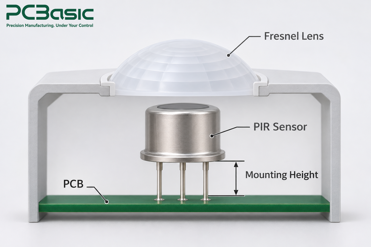
When a design uses an independent PIR sensor mounted on the board alongside a separate Fresnel lens:
• Check Sensor Mounting Height: Verify the sensor mounting height against the assembly drawing. If the specification calls for a specific standoff height, soldering the sensor flush against the board surface can move the sensing element away from the lens’s intended focal plane.
• Optical Position and Orientation: Inspect first-article builds against approved engineering drawings to confirm that the sensor's position, orientation, and alignment tolerances match the optical design requirements of the lens.
When using pre-packaged sensor-and-lens modules or housing assemblies:
• Enclosure Opening Alignment: Verify how the module seats against the internal mechanical stops of the plastic chassis.
• Tolerances and Retaining Features: Mechanical drawings should detail acceptable gap limits between the lens window edge and the outer enclosure wall to limit airflow-induced temperature changes, loose movement, or optical occlusion.
Soldering a PIR motion sensor PCB assembly requires balancing high-volume manufacturing protocols with the thermal and cleanliness limits of the components.
Not all sensing elements can endure high thermal exposure:
• Thermal Limit Verification: Before routing boards through a standard reflow oven, engineering teams must review specific part numbers and original manufacturer soldering guidelines. Whether a component can withstand reflow depends on its specific construction and the component manufacturer’s approved soldering conditions.
• Selective or Hand Soldering: For components sensitive to high peak reflow temperatures, automated selective soldering or skilled manual soldering may be used only where permitted by the component manufacturer’s soldering guidelines.
Discrete PIR sensing circuits can contain high-impedance nodes that are vulnerable to minute surface leakage paths. Stray currents caused by residual flux, ionic contamination, or moisture can generate noise that resembles motion-induced signals:

• Process Compatibility Review: Check the specific sensor component datasheet and lens material compatibility prior to production.
• Cleaning and Drying Requirements: If cleaning is required, use a process approved for the assembled board and follow its drying requirements. For a qualified no-clean process, inspect residues against the project’s acceptance criteria.
Key visual inspection points prior to functional testing are summarized below, together with their acceptance basis:
|
Inspection Item |
What to Check |
Acceptance Basis |
|
Pin Orientation |
Pin 1 indicators, locating tabs, and lead orientation |
Approved assembly drawings and component datasheets |
|
Mounting Standoff |
Spacing between the sensor base and the PCB |
Specified mounting height and tolerances |
|
Surface Cleanliness |
Visible residues around high-impedance traces |
Project visual acceptance criteria |
At PCBasic, first-article inspection helps verify component orientation and assembly workmanship before production continues. For PIR sensor boards, sensor mounting height and positioning can also be checked against customer-approved assembly drawings.

A board that passes simple circuit continuity checks is not automatically ready for field deployment. Validating a PIR motion sensor PCBA requires testing both individual board-level electrical signals and final mechanical and optical performance.
Before installing the board into its final housing:
• Power Stabilization Window: Apply the rated operating voltage and allow the circuit to complete its required power-up settling period. Pyroelectric circuits require time for internal voltages to stabilize before their outputs become reliable.
• Quiescent and Trigger State Checks: Measure idle supply current and output behavior while the board is shielded in a stable thermal environment. For digital outputs, check whether the signal switches as specified; for analog outputs, check whether the signal change relative to baseline matches expectations.
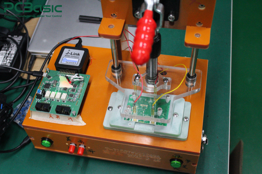
Testing a board outside its enclosure provides only a baseline verification. Full optical validation requires inspecting the completed device inside its final housing:
• Environmental Test Conditions: Place the assembled board into its designated enclosure with the specified Fresnel lens installed. Test performance at agreed-upon target distances, approach angles, target sizes, movement speeds, and ambient-to-target thermal differentials.
• Field-of-View Verification: A simple close-range hand wave confirms that the sensor reacts, but it does not confirm field-of-view (FOV) angles or maximum detection range. Full validation requires verifying coverage boundaries against the product's engineering specification.
Mastering motion sensor PCB assembly requires bridging the gap between rigorous electrical design and precise mechanical execution. Every detail matters—from selecting verified components on the BOM to managing cleaning processes, and from aligning optical datums to running rigorous functional tests using suitable fixtures.
Contract manufacturing partners like PCBasic help streamline this transition by conducting thorough BOM reviews, verifying component pinouts, inspecting first-article builds against mechanical drawings, and executing board-level functional testing per agreement. If validation of enclosed detection ranges is also required, confirm in advance who provides the lens, enclosure, and specific acceptance conditions. Feel free to submit your BOM, assembly drawings, and sensor datasheets to start a project review.
Q1: Why does a PIR board stay triggered or trigger repeatedly?
Before troubleshooting, confirm the design's active output level, power-up settling time, and pulse hold time. If a board remains in its active state or triggers repeatedly without movement, check for airflow causing temperature changes at the sensor or lens, power supply noise, ionic residue across high-impedance inputs, or unapproved passive components exhibiting high thermal drift.
Q2: Can all PIR sensors go through standard SMT reflow ovens?
No. While specialized surface-mount PIR sensors are designed for specified reflow profiles, many traditional through-hole and metal-can units are not approved for standard SMT reflow. Always check the manufacturer's soldering guidelines and package specifications before processing.
Q3: How can procurement teams prevent component substitution issues on PIR boards?
Maintain explicit approved vendor lists (AVL) and approved alternate part lists to the BOM. Require contract manufacturers to obtain formal engineering approval through the agreed change-control process before substituting any passives, ICs, or sensors on the analog front-end.
Q4: What is the recommended way to clean a PIR sensor board after soldering?
Cleaning procedures must be validated against the specific sensor datasheet and lens materials used. If cleaning is required, use a process approved for the assembled board and follow its drying requirements. For a qualified no-clean process, inspect residues against the project’s acceptance criteria.

Assembly Enquiry
Instant Quote



Phone contact

+86-755-27218592
In addition, we've prepared a Help Center. We recommend checking it before reaching out, as your question and its answer may already be clearly explained there.
Wechat Support

In addition, we've prepared a Help Center. We recommend checking it before reaching out, as your question and its answer may already be clearly explained there.
WhatsApp Support

In addition, we've prepared a Help Center. We recommend checking it before reaching out, as your question and its answer may already be clearly explained there.
