Global high-mix volume high-speed PCBA manufacturer
9:00 -18:00, Mon. - Fri. (GMT+8)
9:00 -12:00, Sat. (GMT+8)
(Except Chinese public holidays)
Global high-mix volume high-speed PCBA manufacturer
9:00 -18:00, Mon. - Fri. (GMT+8)
9:00 -12:00, Sat. (GMT+8)
(Except Chinese public holidays)
HomePage > Blog > Knowledge Base > Power Plane in PCBs
Every electronic device needs power. However, how power flows through a circuit can make or break performance. That’s where the power plane comes in. They are neither wires nor traces; instead, they are large copper layers inside a PCB that distribute power evenly.
Think of them as highways. Instead of cars, they carry electrical current. Without them, power delivery gets messy, and voltage drops. Moreover, noise increases, and signals get weak.
If you have ever dealt with a noisy circuit or unstable voltage, power planes might be the missing piece. Let’s break it all down.

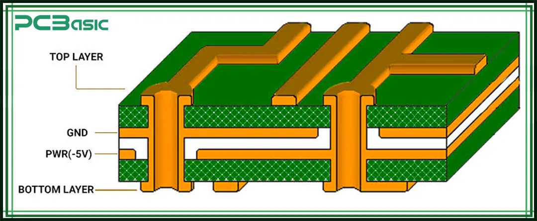
A power plane is a solid sheet of copper inside a PCB. It carries voltage from the power source to different parts of the circuit.
It works alongside a ground plane, which provides the return path. Together, they create a low-impedance power distribution network.
Why not just use traces? Simple. Traces have resistance. That resistance leads to voltage drops, heat, and interference. A PCB power plane, on the other hand, spreads power across a large area. More stability. Less noise. Better performance.
You’ll find power planes in almost every complex PCB, from smartphones to industrial machines. Without them, circuits would be unreliable.
Not all power planes are the same. Here are the main types:
● A full copper layer with no breaks.
● Best for stable power distribution.
● Reduces noise and improves efficiency.
● Divided into sections, each carrying a different voltage.
● Used when multiple power levels are needed.
● It can cause noise if not designed carefully.
● Uses leftover copper instead of a dedicated layer.
● It greatly improves power delivery. However, it is not as effective as
a power plane.
● Common in low-power circuits.
Each type serves a purpose. Choosing the right one depends on the circuit’s needs.
Different circuits require different power plane configurations. Here are some of the most common setups:
● Standard in most PCB designs.
● Reduces impedance and improves signal integrity.
● Keeps power stable.
● Placing them close improves decoupling.
● It helps filter out noise.
● Used in high-speed circuits.

● It is found in complex PCBs with multiple voltages.
● Used in CPUs, GPUs, and high-performance devices.
● This type of configuration requires a precise design to avoid interference.
Each configuration has its benefits. Picking the right one depends on factors like power demand and signal speed.
So why does any of this matter?
Because power planes make circuits more stable. They help in several ways:
There are no sudden voltage drops or weak connections. Power is evenly spread across the board.
Electromagnetic interference (EMI) is a real problem. A solid power plane reduces it. It results in cleaner signals and fewer errors.
Copper conducts heat. Power planes help spread that heat, preventing hotspots.
Power planes work with ground planes to create smooth return paths with less noise. Better signal quality.
If your circuit is struggling with stability, look at the power planes first. They might be the key to fixing the issue.

Adding a power plane is not enough. It has to be designed correctly. A poorly designed power plane can cause more problems than it solves.
Here are some key things to keep in mind:
Power needs a return path. That’s what the ground plane is for. If the power and ground planes are too far apart, the circuit can pick up noise.
Placing them on adjacent layers creates a natural capacitor. This helps smooth out voltage fluctuations and reduces interference.
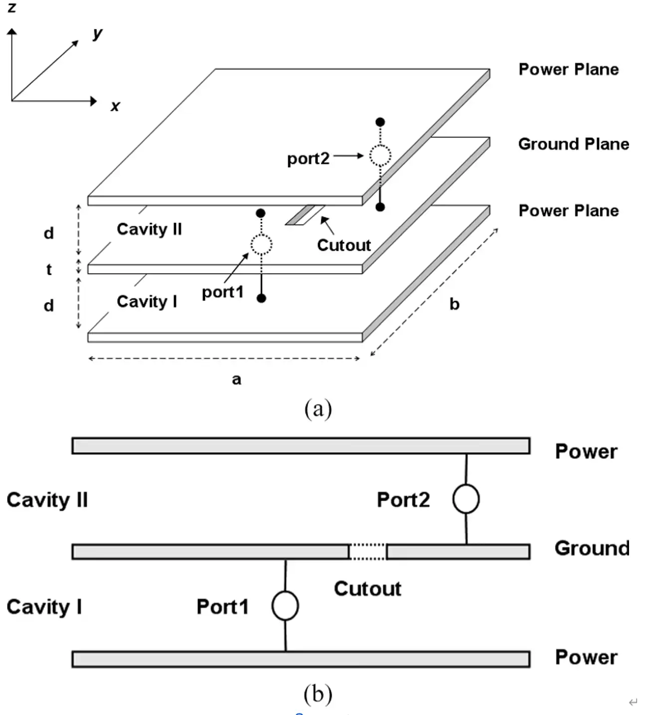
A power plane should be as continuous as possible. Gaps, cuts, or splits can cause problems.
● Signals might not find a clear return path.
● Voltage can become unstable.
● EMI can increase.
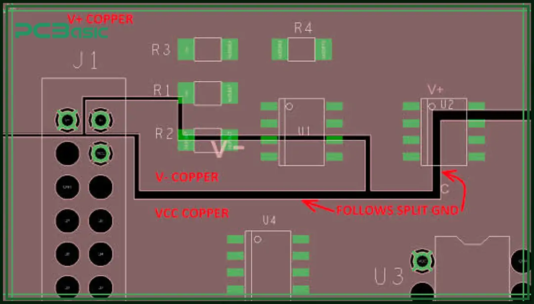
If you need to split a power plane (for multiple voltages), do it carefully. Avoid long gaps and make sure there’s a clear return path.
Vias connect power planes to different layers. Poorly placed vias can create bottlenecks, leading to voltage drops.
Here’s what helps:
● Use multiple vias for high-current paths.
● Place vias near power-hungry components to reduce resistance.
● Avoid long, thin traces connecting to the power plane.
Power planes dissipate heat. That’s a good thing. However, if the plane is carrying too much current, it can still overheat.
To manage heat:
● Use thicker copper layers (e.g., 2 oz) for high-power circuits.
● Add thermal vias to move heat to different layers.
● Keep high-power components near the edge for better cooling.
The larger the loop area, the more EMI you get. Keeping power and ground close together reduces the loop size, lowering interference. This is especially important in high-frequency circuits.
Power and ground planes work together, but they are not the same.
Here’s how they compare:
|
Feature |
Power Plane |
Ground Plane |
|
Purpose |
Voltage distribution |
Offers a return path |
|
Placement |
Place it close to voltage sources |
Close to signal layers |
|
Effect |
Power stabilization |
Reduces noise and EMI |
|
Connection |
Connected to power supply |
Connected to ground |
A good PCB design pairs them closely. This creates a low-impedance power network, making the circuit more stable.
If the power plane is not well-designed, the PCB ground plane will not work effectively either. Both need to be optimized together.
A power plane might seem simple. But getting it right can make or break a PCB design.
They improve power stability, reduce noise, and enhance signal integrity. A well-designed power plane means fewer problems down the road.
If your PCB is struggling with voltage drops, EMI, or heat issues, the power plane might be the culprit. Optimize it, and your circuit will thank you.

Assembly Enquiry
Instant Quote
Phone contact

+86-755-27218592
In addition, we've prepared a Help Center. We recommend checking it before reaching out, as your question and its answer may already be clearly explained there.
Wechat Support

In addition, we've prepared a Help Center. We recommend checking it before reaching out, as your question and its answer may already be clearly explained there.
WhatsApp Support

In addition, we've prepared a Help Center. We recommend checking it before reaching out, as your question and its answer may already be clearly explained there.
