Global high-mix volume high-speed PCBA manufacturer
9:00 -18:00, Mon. - Fri. (GMT+8)
9:00 -12:00, Sat. (GMT+8)
(Except Chinese public holidays)
Global high-mix volume high-speed PCBA manufacturer
9:00 -18:00, Mon. - Fri. (GMT+8)
9:00 -12:00, Sat. (GMT+8)
(Except Chinese public holidays)
HomePage > Blog > Knowledge Base > How to Wire a Potentiometer?
A potentiometer is used to adjust and control the electric current flow in a printed circuit board. A very simple example is a faucet. You can effortlessly control the water flow by controlling the faucet. So a potentiometer is incorporated for use in day-to-day things like volume control devices.
Let’s define this in a very simple way. A potentiometer is a three-terminal changeable resistor. You can use it to adjust the voltage in the circuits. However, what is its basic use? It modifies and divides voltage, allowing control over the output voltage of a device. For instance, Terminal 1 (Input), Terminal 2 (Wiper), and Terminal 3 (Ground).
They are used throughout circuits to vary functions such as volume, light intensity and motor speed. Potentiometers are used as volume controls in audio equipment and light dimmers by tightening them directly so the sound or brightness is less intense. You will find these elements in stereo devices to make home light dimmer changes.
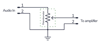
A potentiometer functions by altering resistance – and, therefore, the flow of current in a circuit. One common application in audio equipment is lowering the volume by turning a knob on the potentiometer. This will decrease the electrical signal sent to speakers so we can hear sound quieter. Simple potentiometers, but very practical for adjusting anything that needs levels at least intermediate.
The pinout is the arrangement of pins on a potentiometer which serve as individual connections to various components within an electrical circuit. Usually, potentiometers have 3 pins or, alternatively, 5. The potentiometer's resistance is controlled by using these pins. The pinout configuration is important because this dictates how you will wire the potentiometer.
These 3-pin potentiometers are the most widely used types. These pins include:
Pin 1 -Power source.
Pin 2 – The wiper, which is the centre pin that you can adjust.
Pin 3 – Connects to ground.
5-Pin Potentiometer (sometimes referred to as 6-pin): They are not so widely used and usually can be found in specialized equipment. 5-pin potentiometers are more commonly dual-control-oriented configurations. For example, they can tune two parameters at once in 2-dimensional devices (e.g., volume and bass on audio gear).
Knowing the pin configuration will help you wire your potentiometer properly for it to work in a way that appeals to you. Faulty wiring can lead to failure, or ruin the potentiometer and other parts of your circuit.

Time is money in your projects – and PCBasic gets it. PCBasic is a PCB assembly company that delivers fast, flawless results every time. Our comprehensive PCB assembly services include expert engineering support at every step, ensuring top quality in every board. As a leading PCB assembly manufacturer, we provide a one-stop solution that streamlines your supply chain. Partner with our advanced PCB prototype factory for quick turnarounds and superior results you can trust.
Pinouts will differ depending on the function and type of potentiometer used. The pin configuration defines the way in which resistance is applied across the circuit. An easy 3-pin potentiometer, provided you keep controls uncomplicated, is a good example. General tasks (such as volume or light intensity adjustment).
It is likely that applying RTP to resistance would also flip around and impose in a manner not suitable for device operation.

To wire a potentiometer, follow these steps to properly pot and against circuit problems. Good wiring practice not only helps in the smooth voltage adjustment, but it can also help you to connect multiple components, i.e., LEDs or motors on a potentiometer, for example
Materials to Prepare Before You Begin
3-pin or 5-pin potentiometer
Power supply (battery or external power)
Jumper wires for connections
Multimeter- to test voltage.
A 3-pin potentiometer is perfect for easy circuits, especially simple light dimming or volume control jobs, but it is impossible to cut into an IC instrument. Those situations will call for something a bit more complicated, but most simple installations can get by on just the 3-pin option. Have the circuit board ready at an operational stage.
When you have all the material, connect the Potentiometer with the Power Source. Follow these steps:
Pin 1 —Positive terminal of power source
Connect ground to Pin 3 using a jumper wire.
Connect the signal to a component you want in behaviour, which can be LED or motor.
It alters the voltage output, by moving the wiper over a resistive track inside the potentiometer. That movement permits accurate control that is well suited to responsibilities along with setting the brightness of an LED or controlling the speed of motors.
The wiper pin controls the connected load. This pin usually has to be connected to the output of the device you want to control (e.g., an LED or motor). The wiper moves in tandem and travels along the resistive track, altering voltage, which then allows control to be smooth.
For example:
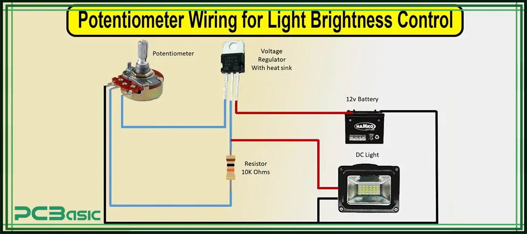
Connect an LED to the wiper pin and vary its brightness by rotating the potentiometer.
The slider controls the speed of the motor when connected to the wiper pin
You will face some problems when you work with potentiometers. Here’s how to troubleshoot:
Output: If the potentiometer is not working, check connections. Check that the current and voltages you want to use are within what the LED or motor can handle.
Output Varies: A key reason for inconsistent performance is poor or loose connections. Check the wiring again and ensure that every terminal is tight.

A potentiometer has 3 pins: Vcc, Output, and GND. Connect these to the voltage source, ground, and output for the potentiometer. This means that when the wiper moves, it also changes in voltage, which is useful for tuning circuits.
A voltage divider is a circuit composed of two serial resistors and can be seen as an adjustable potential between any 2 points similar to this. This arrangement is widely aerial in audio ascendancy circuits for bursting the arresting and actuality able to calmly acclimatize the volume.
In the case of an LED dimmer, it will adjust brightness by managing the current to your LED via a potentiometer. You can brighten or dim the LED by moving this wiper.
A potentiometer is a control that can set levels, such as the volume in audio equipment. And this we are able to do by varying frequencies and impedance levels, allowing for easy control of noise levels!

Now you know the proper wiring and usage of potentiometers. Available in lighting dimmers, motor controls, and audio systems. To place potentiometers on a high-quality PCB, get in touch with PCBasic for best-in-class circuit board solutions.

Assembly Enquiry
Instant Quote
Phone contact

+86-755-27218592
In addition, we've prepared a Help Center. We recommend checking it before reaching out, as your question and its answer may already be clearly explained there.
Wechat Support

In addition, we've prepared a Help Center. We recommend checking it before reaching out, as your question and its answer may already be clearly explained there.
WhatsApp Support

In addition, we've prepared a Help Center. We recommend checking it before reaching out, as your question and its answer may already be clearly explained there.
