Global high-mix volume high-speed PCBA manufacturer
9:00 -18:00, Mon. - Fri. (GMT+8)
9:00 -12:00, Sat. (GMT+8)
(Except Chinese public holidays)
Global high-mix volume high-speed PCBA manufacturer
9:00 -18:00, Mon. - Fri. (GMT+8)
9:00 -12:00, Sat. (GMT+8)
(Except Chinese public holidays)
HomePage > Blog > Knowledge Base > How to Solder Wires to a Circuit Board?
The soldering is very important for the connection of components on the PCB board and other electronic circuits. The soldering wires and other components are the main factors that help to accurate working of any circuit and project. The filler metal of melting points less than 450 degrees is used for the connection of two metallic points.
For PCBs, board soldering is the main component of board creation that helps to join different components on the board by connecting their pins. Most used solder is made of tin and lead, which have a melting point of 185 degrees. The melting of solder makes solder conductive joins after cooling at a certain point. Here we will learn how the soldering process is done and its importance. So let's get started.

The soldering process involves solder melting on wires, electronic components, or PCB boards to make connections between certain points or components. For performing the soldering process, soldering iron is the main component that melts the solder on connection points, and some other tools are solder wick, solder sucker, etc.
Soldering is considered the key component of electronic manufacturing, PCB board creation, and project creation. The solder of the soldering process comes in different alloy types, such as tin-lead, tin-silver, etc. Normally, lead-free solders are used to prevent any hazards to human life.
Solder comes in different types, and solder wire is among them. Solder wires come with different features that are used to perform special applications based on temperature requirements. Solder wires come in different types based on the type of solder used for your projects and their prices.
The common types of solder wires are lead alloy solder and lead-free solder. Lead solder wire is made with lead and tin alloy. Tin uses lead since it has low melting points. The ratio of tin-lead alloy is 63:37, which is mostly used for electronic component connections.

Soldering Iron:
● A soldering iron is used to provide heat in a controlled way for melting solder. Use solder iron that provides different temperature features, such as from 300 to 400 centigrade. Use tip dimensions of one millimeter to two millimeters for soldering wires. Larger diameter tips are good to use for larger-component connections.
● Low wattage, about 15 to 40 Watts, is used for the connection of components on boards, and high wattage (60 to 140 Watts) is used for heavy loads.
Solder Wire:
● Filler metallic components are provided by the solder wire for making the connections. Lead-free solders needed higher temperatures, and normally rosin core solders used a diameter of 0.5mm to 1mm, which is ideal.
Soldering Stand and Sponge:
● At the time of the soldering process, when you are not using a hot iron, place it on the soldering stand. The sponge is used for cleaning the tip of the iron and also removing the extra solder on the board to avoid any corrosion and extra damage to the board.
Flux and Cleaner:
● On the PCB board, soldering surface flux removes the impurities and also avoids oxides on the metallic surface of the board. Flux provides the required solder joints. Cleaning flux residues isopropyl used.
Safety Gear:
● Before the soldering process, you must follow safety precautions. Use safety glasses to protect your eyes from any hazardous materials. Also, your must-lab has a proper ventilation system.
Follow these points before the soldering process.
1. First of all, cut the wires to the required strength and leave some extra points for proper insertion in holes.
2. For removing the wire insulation, different tools, such as strippers, remove insulation.
3. The main tip for accurate heat transfer and proper joint creation—pre-tinning of wire—is needed.
4. Perform accurate cleaning of the board before soldering. Normally, different solutions, such as isopropyl alcohol, are used to help remove oxides on the board and other impurities.
5. For an easy soldering process, set the board at the proper point to avoid any distortion during solder applications.
6. Now connect all components of your design or project at their respective positions for proper work.
7. Try to use a heat sink where you are soldering components since it can save components from getting damaged due to high temperatures.

● Tinnig of the iron tip helps to easily connect solder on board and transfer heat to connection points. For this process, connect the solder with a hot iron tip for small quantities. Then apply solder until the tip has a coating of solder.
● The proper connection of wire and component is important for the soldering process.
● If you are connecting components on board with the use of a plated through-hole process, then connect wires on the side where components are connected. For single-layer board-connected components on the soldering side
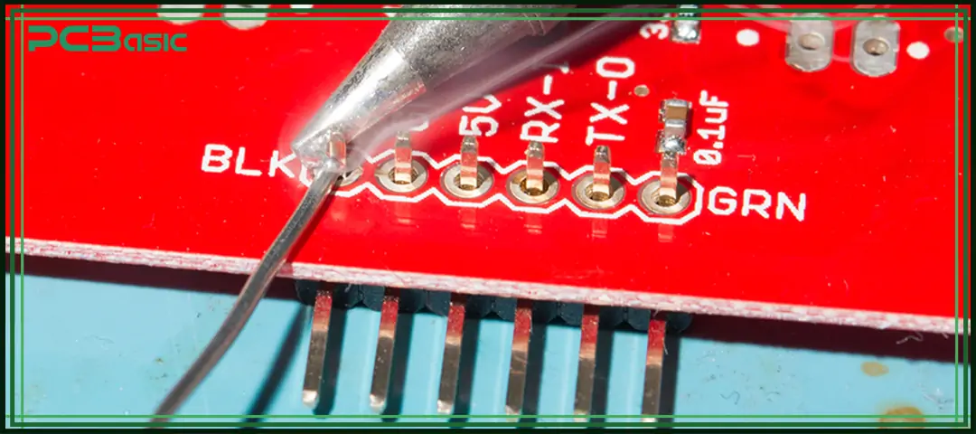
● For accurate soldering, put tinned iron on the wire lead and pad at the same time. Put iron on that point for some time until the wire and the pad get hot without moving the wire.
● Put solder on the pad and wire close to the tip of the iron. Solder melts and passes about wire and pad. When the solder moves to the joint, remove the iron.
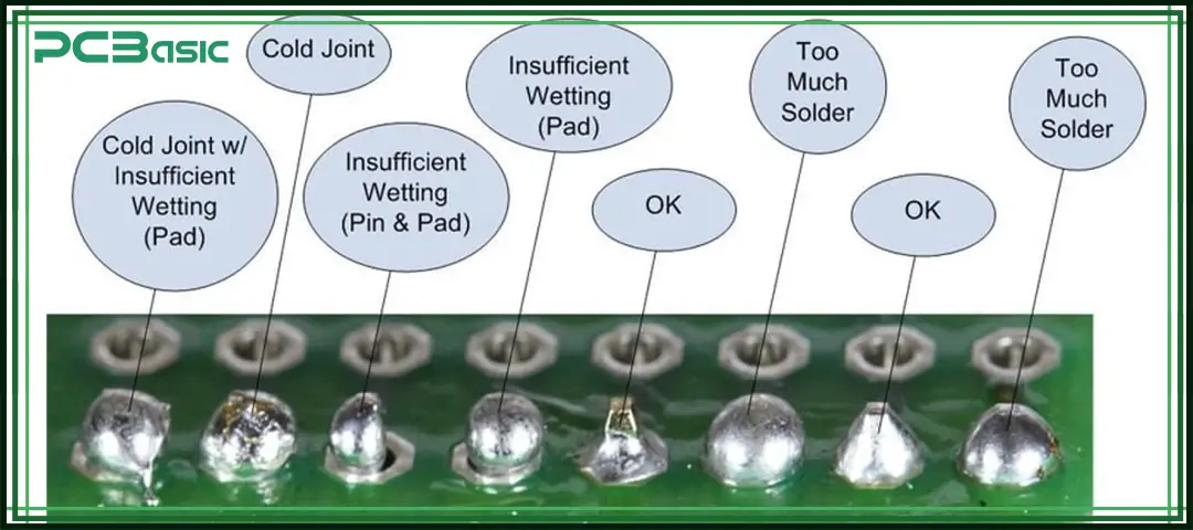
● In this step, after removing the iron tip, wait for some time for the solder joint to cool. Check that joins are created accurately with solder fillets over the wire. If you find any cracks again, make joints.

● The cold joint is the result when the solder is not melted completely. To avoid solder joints, use a completely heated soldering iron and provide the required soldering temperature.
● The dry solder joint results when the solder is not wet properly. It makes a weak electrical connection. The main causes of dry solder joints are oxides, faulty soldering methods, improper heat, etc.
● It is caused by two or more pad connections as a result of larger solder use and makes a bridge-like configuration. These bridges have a bad effect on board working, such as short circuits, and also damage connected components.
● Solder balls are small, sphere-like blobs that occur during soldering on board. That has a bad effect on working on board. They are mainly seen on the side of chip components and pin connectors. The main causes of solder balls are:
○ Excessive solder paste
○ Incorrect Reflow Profile:
○ Contaminated PCB Surface:
○ Component Misconnections
● The contact rating of solder contact is affected due to oxidation occurring on the pad and causing bad, faulty soldering. As a result, the solder is not accurately connected to the pad and makes loose connections.
● Use the accurate soldering iron for the soldering process; most used are cordless.
● Use the proper third hand or vice.
● Apply a thin solder to make the project joint.
● For beginners, the recommended solder is 60/40 solder.
● The right size must be proper
● Before using the soldering iron set, the required temperature
● Use the soldering iron with your right hand and hold the cool end.
● Put iron first on the joint and then on the solder.
● Not putting solder for a longer time can cause a larger blob.
● Frequently clean the tip with iron wool or a wet sponge.
● Avoid high pressure on the soldering iron.
● Do practice to become an expert in soldering.
● Try to use soldering tips that are configured according to pad size and leads of components.
● For accurate heat transfer to the joint set, the soldering iron tip is accurately tinned with the use of a certain quantity of solder.
● Connect the heat sink close to sensitive components to avoid any damage.
● To avoid any crack on the board, perform preheating at a larger copper fill point.
● Follow the through-hole component connection, then the surface mounting connection for a large number of connections on boards.
● For finding any faults, check cracks, holes, or short circuits for any soldering faults. Use a magnifying glass to check faults.
The soldering is a basic and important component of the electronic industry and circuit creation. This process helps to make our design practical. There are different tools used for creating the connection in the soldering process. This process is now needed to learn all basic to advanced levels of electronics engineers. Without learning this process, you will not be a professional engineer to make your project practical and working. Before using a soldering iron, follow some precautions, such as wearing goggles, gloves, and other protection accessories to work in environments.

Assembly Enquiry
Instant Quote
Phone contact

+86-755-27218592
In addition, we've prepared a Help Center. We recommend checking it before reaching out, as your question and its answer may already be clearly explained there.
Wechat Support

In addition, we've prepared a Help Center. We recommend checking it before reaching out, as your question and its answer may already be clearly explained there.
WhatsApp Support

In addition, we've prepared a Help Center. We recommend checking it before reaching out, as your question and its answer may already be clearly explained there.
