Global high-mix volume high-speed PCBA manufacturer
9:00 -18:00, Mon. - Fri. (GMT+8)
9:00 -12:00, Sat. (GMT+8)
(Except Chinese public holidays)
Global high-mix volume high-speed PCBA manufacturer
9:00 -18:00, Mon. - Fri. (GMT+8)
9:00 -12:00, Sat. (GMT+8)
(Except Chinese public holidays)
HomePage > Blog > Knowledge Base > About Circuit Board Resistors: All You Want to Know
Circuit board resistors are fundamental components in electronic circuits. These small but significant elements control electrical current and voltage flow in printed circuit boards (PCBs).
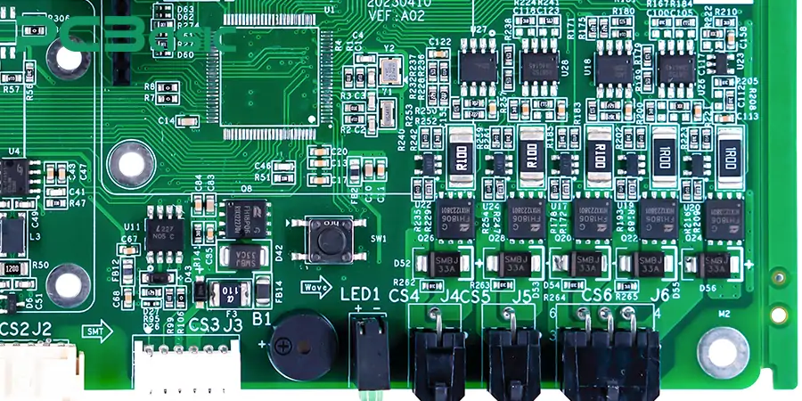
Resistors are the most common components we'll see on a circuit board. These building blocks of electronic design perform several key functions:
● Controlling current flow in circuits
● Dividing voltage between components
● Creating heat in specific applications
● Protecting sensitive components from damage
● Setting proper operating conditions
Modern electronics rely heavily on resistors to maintain stable and reliable circuit operation. PCB designers see resistors as the "traffic controllers" of electrical current, ensuring each component gets the right amount of current and voltage to function properly.
Resistors serve multiple critical roles on circuit boards. They protect sensitive components by limiting current flow to safe levels and establishing proper bias conditions for active components like transistors and integrated circuits. Circuit designers use them to create timing circuits, filter unwanted signals, and set gain levels in amplifier circuits.
Ground applications often need precise current control. LED circuits need resistors to prevent LEDs from drawing too much current and burning out. Analog circuits use resistors to create voltage dividers that provide specific voltage levels for various components.
Resistors are vital to power management. They dissipate excess energy as heat and protect other components from damage caused by excessive voltage or current. Digital circuits need pull-up or pull-down resistors to ensure proper logic levels and prevent floating inputs that could cause unpredictable behavior.
Electronics design and repair professionals must understand how resistors work in circuit boards. The next sections will deeply explore various types of resistors and their specific applications.
Today many different resistors are used in Circuit Boards, each with its purpose. Let's look at the most common ones and what makes them special.
Carbon composition resistors are the oldest ones we can find. They combine carbon powder with ceramic and can handle high-energy pulses at temperatures up to 350 degrees Celsius. They work with voltages up to 15kV.
Carbon film resistors give us resistance ranges from 1 ohm to 22 megohms with tolerances between ±5% to ±0.5%. They're perfect for general-purpose applications.
Metal film resistors mark a big step forward in precision. These components deliver resistance ranges from 1 ohm to 1 megohm, with impressive tolerances of ±1% to ±0.01%. Their temperature coefficient ranges from ±15 to ±25 ppm/°C.
Metal oxide film resistors outperform other types in several ways:
● Power rating capacities
● Voltage handling
● High-temperature operation up to 450°C
As per our experience, wire-wound resistors excel at precision and power handling. They provide resistance values from 0.1 ohms to 10 Kilo ohms, with tolerances ranging from ±5% to ±0.02%.
Ceramic composition resistors are great at handling high-energy pulses. They are often found in high-voltage power supplies and R-C snubber circuits.
Fusible resistors work in two ways - they act like normal resistors until the current goes above a set limit, and then they work as fuses. Many high-end electronic products like amplifiers and television sets use them.
Trimmer resistors, often known as trim pots, allow us to properly adjust resistance levels. Trimmer resistors are suitable for calibration since they can withstand several hundred cycles.
Thermistors are useful for temperature sensing.
Types of Temperature Coefficient:
1. Negative temperature coefficient (NTC)
2. Positive temperature coefficient (PTC)
NTC thermistors can be incredibly precise—up to 0.1°C or 0.2°C when measuring temperatures between 0°C and 70°C.
Varistors protect delicate circuits from overvoltage situations. They withstand high-peak pulse currents well.
In the absence of light, photoresistors exhibit low resistance, whereas in the presence of light, they exhibit high resistance.
Magneto resistors function differently; as the strength of the magnetic field increases, so does their resistance, making them useful for position sensing.

Reading resistor values on circuit boards might look tricky at first. The good news is we have two reliable ways to identify these values. Let's look at both methods to make identification quick and accurate.
Through-hole resistors follow a color-coding system that we can decode with this simple method:

Most resistors come with four or five bands. We read these bands from left to right, and the tolerance band appears last - usually in gold or silver.
● SMD Resistors Labeling Scheme:
○ Uses a code made up of three or four numbers.
● 3-Digit Code:
○ First two digits: Represent the most significant figures.
○ Third digit: Indicates the number of zeros to add.
○ Example: "103" = 10 + 3 zeros = 10,000 ohms (10kΩ).
● 4-Digit Code:
○ Provides more precision, especially for resistors with narrow tolerance.
○ Final digit: Acts as a multiplier.
● These labeling systems make it easy to identify circuit board resistor values.
|
Code |
Device |
Manufacturer |
Base |
Package |
Leaded Equivalent/Data |
|
01 |
Gali-1 |
MC |
AZ |
SOT89 |
DC-8GHz MMIC amp 12dB gain |
|
02 |
Gali-2 |
MC |
AZ |
SOT89 |
DC-8GHz MMIC amp 16dB gain |
|
03 |
Gali-3 |
MC |
AZ |
SOT89 |
DC-3GHz MMIC amp 22dB gain |
|
04 |
Gali-4 |
MC |
AZ |
SOT89 |
DC-4GHz MMIC amp 17.5 dBm |
|
02 |
MRF5711L |
Mot |
X |
SOT143 |
npn RF MRF571 |
|
04 |
MRF5211L |
Mot |
X |
SOT143 |
npn RF MRF521 |
|
0 |
2SC3603 |
Nec |
CX |
SOT173 |
Npn RF fT 7GHz |
|
p01 |
PDTA143ET |
Phi |
N |
SOT23 |
pnp dtr 4k7+4k7 |
|
t01 |
PDTA143ET |
Phi |
N |
SOT23 |
pnp dtr 4k7+4k7 |
|
02 |
BST82 |
Phi |
N |
- |
n-ch mosfet 80V 175mA |
|
p02 |
PDTC143ET |
Phi |
N |
SOT23 |
npn 4k7+4k7 bias res |
|
t02 |
PDTC143ET |
Phi |
N |
SOT23 |
npn 4k7+4k7 bias res |
|
-04 |
PMSS3904 |
Phi |
N |
SOT323 |
2N3904 |
|
02 |
DTCC114T |
Roh |
N |
- |
50V 100mA npn sw + 10k base res |
|
03 |
DTC143TE |
Roh |
N |
EMT3 |
npn dtr R1 4k7 50V 100mA |
|
03 |
DTC143TUA |
Roh |
N |
SC70 |
npn dtr R1 4k7 50V 100mA |
|
03 |
DTC143TKA |
Roh |
N |
SC59 |
npn dtr R1 4k7 50V 100mA |
|
04 |
DTC114TCA |
Roh |
N |
SOT23 |
npn dtr R1 10k 50V 100mA |
|
04 |
DTC114TE |
Roh |
N |
EMT3 |
npn dtr R1 10k 50V 100mA |
|
04 |
DTC114TUA |
Roh |
N |
SC70 |
npn dtr R1 10k 50V 100mA |
|
04 |
DTC114TKA |
Roh |
N |
SC59 |
npn dtr R1 10k 50V 100mA |
|
011 |
SO2369R |
SGS |
R |
SOT23R |
2N2369 |
|
005 |
SSTPAD5 |
Sil |
J |
- |
PAD-5 5pA leakage diode |
|
010 |
SSTPAD10 |
Sil |
J |
- |
PAD-10 10pA leakage diode |
The right resistor choice for a circuit board depends on several vital parameters. Let me walk you through everything that helps determine the best pick for our PCB design.
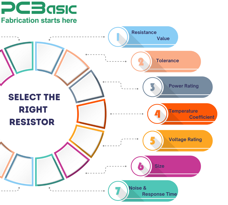
The exact resistance value needed by our circuit comes first. The current and voltage requirements of our design determine this value. We pick standard values from the E-series (E12, E24, E96) because they are readily available.
The tolerance rating shows how much actual resistance might differ from the nominal value. Here's what we usually pick:
● ±1% for precision applications
● ±5% for general-purpose circuits
● ±0.1% for high-precision measurement circuits
Power rating tells us the heat a resistor can safely handle. We calculate the maximum power using P = I²R or V²/R, then pick a resistor rated at least 2x this value to stay safe.
Temperature coefficient (tempco) shows how resistance changes with temperature. This is a vital factor in:
● Temperature-sensitive applications
● Outdoor equipment
● High-power circuits
Each resistor has its maximum working voltage. Our circuit's operating voltage plus safety margin should not exceed this rating.
Physical dimensions play a big role in modern PCB design. We need to think about:
● Available board space
● Component height restrictions
● Thermal management requirements
● Assembly method (SMD vs through-hole)
Resistor noise characteristics matter in sensitive analog circuits. Metal film resistors work better than carbon composition types when it comes to noise performance.
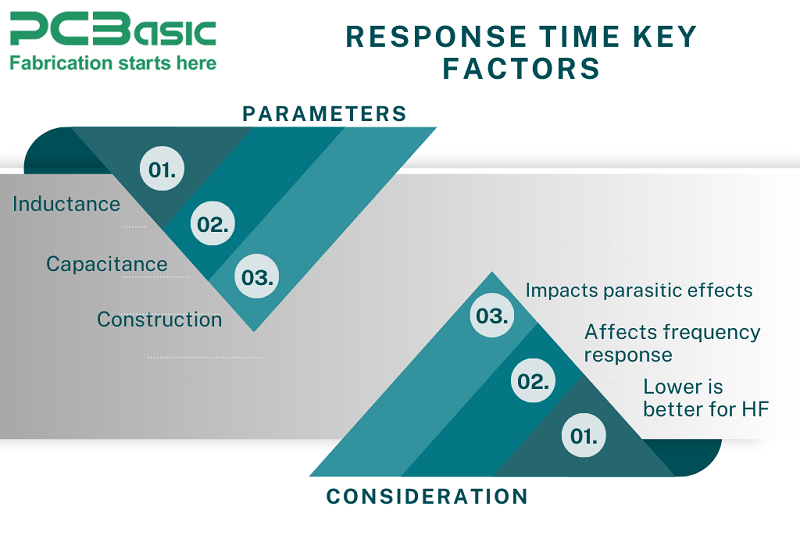
We need to pay careful attention to the response time of High-frequency applications. Here are the key factors:
Resistors play many vital roles in electronic designs. Let's look at their common applications and how they boost circuit functionality.
We can use voltage dividers to get a lower voltage from a higher voltage source. These setups need two or more resistors in series to create specific voltage ratios:
|
Input Voltage (V) |
Resistor Ratio |
Output Voltage (V) |
|
12 |
1:1 |
6 |
|
5 |
2:1 |
1.67 |
|
3.3 |
3:1 |
0.825 |
Current limiting protects sensitive components effectively. Here are some common uses:
● LED brightness control
● Input protection for microcontrollers
● Power supply current regulation
● Motor current control
● Sensor input protection
Pull-up and pull-down resistors help establish defined logic states in digital circuits. Values typically range from 1kΩ to 100kΩ based on the application. These resistors prevent floating inputs that could lead to unpredictable behavior in microcontroller circuits.
Biasing networks help set proper operating points for active components. The configuration allows us to:
● Set DC operating points for transistors
● Configure gain stages in amplifiers
● Control input impedance
● Keep circuit operation stable
● Make power consumption efficient
Resistors often perform multiple functions in our designs. A single resistor can work as both a current limiting and biasing element in an LED driver circuit. Voltage dividers also work well with biasing networks in analog circuits.
Resistors excel at impedance matching between circuit stages. This becomes especially important in high-frequency designs where signal quality matters most.
Smart selection and placement of resistors ensure optimal circuit performance and protect sensitive components. Modern electronic design relies heavily on these versatile components.
Circuit board resistor testing needs careful attention to detail and the right methods. Let's look at proven ways to check if our resistors work properly.
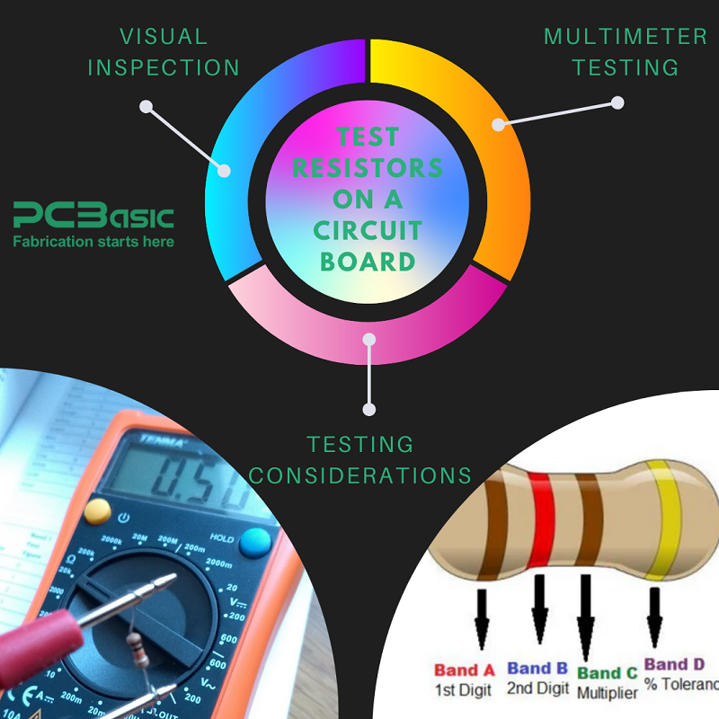
A full visual check of the resistor comes first. We need to watch out for:
● Discoloration or burning marks
● Physical damage like cracks or chips
● Color band deterioration
● Strange changes in component color
We used a digital multimeter to get accurate resistance measurements. Here's what we need to do:
1. Switch off all power to the circuit board
2. Set the multimeter to resistance (Ω) mode
3. Place probes on resistor leads
4. Compare readings with expected values
5. Document any major differences
Acceptable variations usually stay within ±5-10% of the labeled value. High-precision applications might need stricter tolerances.
Several factors matter when we test resistors in-circuit:
This happens because:
● Parallel current paths affect readings
● Other components influence measurements
● Circuit design affects testing accuracy
We'll get the most accurate results by:
● Testing critical resistors by lifting one lead
● Using guard techniques for precise measurements
● Verifying readings in both directions
● Comparing results with design specifications
● Automated testing environments use:
● In-circuit testing equipment
● Optical inspection systems
● X-ray inspection for hidden defects
Variations beyond the component's tolerance range point to potential problems that need more investigation or replacement.
Resistors are the lifeline components defining modern electronics design and functionality in circuit boards. The article addresses everything in such vital components ranging from simple principles to advanced applications. PCB designers must understand the types, values, and applications of resistors in establishing reliable circuits. Various types of resistors are available for specific applications. They restrict current flow, safeguard delicate components, and accurately divide voltage.
Choosing the right resistors takes a little care with the specs. Our deep dive into color codes, SMD markings, and how to pick them gives you the know-how to make smart choices. These skills are super handy for getting insights, especially when we need to fix existing circuits or whip up new ones. Testing methods range from visual inspection to accurate measurements by a multimeter and checking the reliability of circuits. Quality control is ensured by proper testing methods. They point out potential risks before system operations are affected.
With advancements in technology, circuit board resistors are continually upgraded. They offer higher precision, reliability, and functionality. Since they form the core of electronic design, they are indispensable. Engineers employ them to design the fastest method of creating reliable circuits for modern engineering needs.

Assembly Enquiry
Instant Quote
Phone contact

+86-755-27218592
In addition, we've prepared a Help Center. We recommend checking it before reaching out, as your question and its answer may already be clearly explained there.
Wechat Support

In addition, we've prepared a Help Center. We recommend checking it before reaching out, as your question and its answer may already be clearly explained there.
WhatsApp Support

In addition, we've prepared a Help Center. We recommend checking it before reaching out, as your question and its answer may already be clearly explained there.
