Global high-mix volume high-speed PCBA manufacturer
9:00 -18:00, Mon. - Fri. (GMT+8)
9:00 -12:00, Sat. (GMT+8)
(Except Chinese public holidays)
Global high-mix volume high-speed PCBA manufacturer
9:00 -18:00, Mon. - Fri. (GMT+8)
9:00 -12:00, Sat. (GMT+8)
(Except Chinese public holidays)
HomePage > Blog > Knowledge Base > Circuit Board Capacitor – Your Ultimate Guideline
But, with so many types of capacitors available, you may experience a hard time trying to choose the right one for your project. Additionally, there are several aspects that you must consider when choosing the best capacitor. Failure to use the suitable capacitor may lead to issues in the future, or your device even getting damaged.
Read this article as we tell you more about capacitors, the types available, how they work, and some of the factors to consider when choosing the correct one.
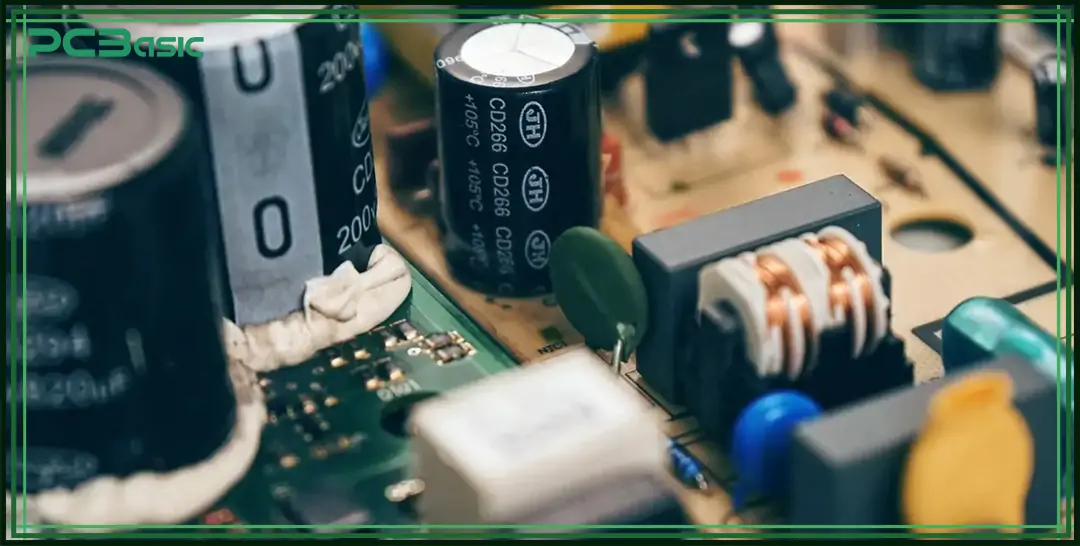
Capacitors store electric charge to help regulate voltage and filter out noise, acting like rechargeable batteries that provide bursts of power as needed. You'll find them on most circuit boards, whether in phones, toys, appliances, or spacecraft. Without capacitors keeping voltage levels stable, your devices wouldn't function reliably.
Capacitors come in different types suited for various circuit applications. From tiny ceramic chips and film rollers to larger aluminum electrolytic and tantalum varieties. Each has specialized properties affecting aspects like capacitance, voltage handling, and frequency performance.
No matter the style, all capacitors have the same basic construction of two conductors separated by an insulator. It's this simple yet effective design that allows them to briefly stockpile electric charge like reservoirs in our digital devices.
Circuit boards require various types of capacitors to function properly. Different capacitor types have unique characteristics that make them suitable for different applications.
Let's take a closer look at some of the most common capacitor types found on circuit boards.
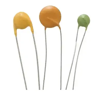
Ceramic capacitors utilize materials like titanium dioxide or barium titanate as the insulating dielectric layer. This lends them noteworthy attributes that are well-suited for high-frequency applications. The ceramic dielectric material provides tighter capacitance tolerances than other types while maintaining stable values even over wide temperature ranges.
Additionally, ceramic's compact size allows sizable capacitance values to be packaged extremely small. This miniaturization, along with ceramics' low equivalent series resistance (ESR) and low losses at radio frequencies and above, explains their widespread usage. Ceramic capacitors are commonly employed for tasks like noise decoupling on power rails where space is limited.
· Capacitance range from 1pF to 1μF
· Withstand voltages up to 100kV
· Operate from -55°C to 200°C
· Inexpensive
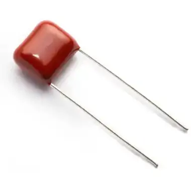
Film capacitors utilize thin plastic films like polyester or polypropylene as the dielectric layer. Their self-healing properties stem from ruptures in the film layer repairing themselves over time. This confers unmatched reliability, enabling film capacitors to last over a million hours of usage.
Additionally, film capacitors maintain stable, consistent capacitance values even as environmental factors like temperature vary. These traits make film capacitors well-suited for applications requiring precision and longevity where tight component tolerances are paramount.
· Capacitance ranges from 1pF to 10μF
· Self-heal for over 1 million hours of use
· Tolerances as tight as 1%
· Low ESR for high-frequency operation
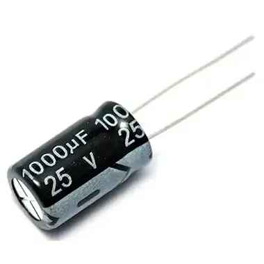
While larger in size than other capacitor types, electrolytic capacitors utilize an extremely thin etched aluminum or tantalum foil with an insulating oxide layer grown between them to achieve by far the highest capacitance values. This compact design results in energy densities far greater than other components, enabling electrolytic capacitors to be ideal for energy storage and bulk smoothing of power supply voltages.
· Capacitance values from 1μF to several farads
· Handles voltages up to 600V
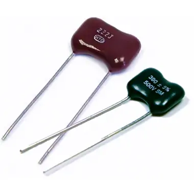
Mica's unique crystalline structure provides sheets of interleaved mica and metal electrodes with unrivaled stability. Mica capacitors maintain precision capacitance values unaffected by temperature, humidity, or environmental factors.
These rugged components perform reliably for decades in applications demanding extraordinary longevity and tolerance stability.
· Operate from -55°C to 125°C
· Tolerances within 1%
· Operating frequencies from audio to microwave
Capacitors are very vital in circuit boards since they perform many essential functions in circuit boards. Some of the applications of capacitors include filtering, coupling, decoupling and bypassing.
This is how they perform each of these roles.
One of the main reasons for adding capacitors to a circuit is to filter it. They are able to remove any high-frequency fluctuations and noise from the power supplies and the signals, and deliver a clean, direct current for the smooth running of the circuits.
Coupling capacitors enable signals to pass through while at the same time providing a barrier to any DC that may be present. This is important for converting AC signals from one stage to the other in a circuit. Coupling caps are important because without them, your audio would not work, or microcontrollers would not be able to communicate properly.
Decoupling capacitors regulate the voltage levels and provide the temporary current demand of the integrated circuits. When an IC (integrated circuit) is turned on or off quickly, it creates dips and spikes. Decoupling caps located right beside the ICs offer backup power momentarily to make up for this.
Bypass capacitors, a type of decoupling cap, provide a low-impedance path to the ground for high-frequency noise. They regulate voltage levels to remain constant in cases of fluctuating loads to avoid breakdowns. Without bypass, computer chips would fail from their own accord due to the speed.
Capacitors are very important in circuit boards - they guarantee a steady power supply, are free from interferences, and are suitable for most contemporary electronics.
 About PCBasic
Time is money in your projects – and PCBasic gets it. PCBasic is a PCB assembly company that delivers fast, flawless results every time. Our comprehensive PCB assembly services include expert engineering support at every step, ensuring top quality in every board. As a leading PCB assembly manufacturer, we provide a one-stop solution that streamlines your supply chain. Partner with our advanced PCB prototype factory for quick turnarounds and superior results you can trust.
The basic principle behind how a capacitor works is utilizing an electric field. It consists of two conductors separated by an insulator known as a dielectric. When a voltage is applied across the conductors, electric charges of equal magnitude but opposite polarity build up on each surface of the dielectric.
The conductor connected to the positive terminal gains negative charges, while the one attached to the negative gains positive charges. These oppositely charged plates attract each other but are prevented from touching by the dielectric between them. Energy gets stored in the electric field created within the capacitor.
The amount of charge a capacitor can store is determined by its capacitance value, which depends on the geometry of the conductors and the nature of the dielectric. Larger plates and a dielectric with higher permittivity allow more charge to accumulate.
When a circuit board uses a capacitor, it creates a structure that takes advantage of this principle. The copper tracks and sometimes entire planes act as the conductive plates. The FR-4 board material serves as the dielectric insulator between them.
During operation, capacitors on a PCB can absorb transient spikes by quickly charging and discharging to provide stable power rails as needed by various loads like processors. Their ability to store localized energy near components ensures smooth, reliable functionality of modern electronics.
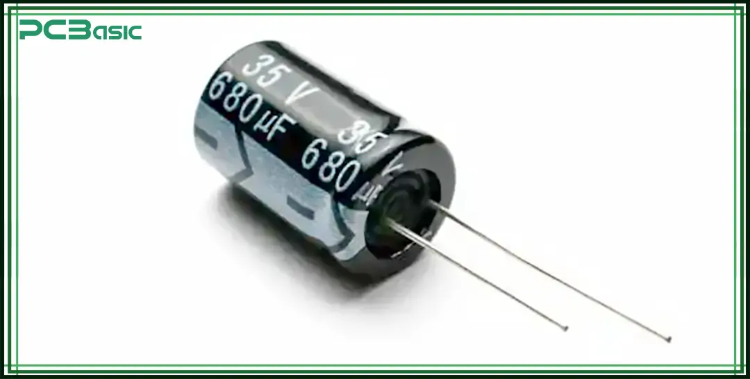
PCB capacitor identification is an important skill for any electronics engineer or hobbyist. Correctly identifying the key markings on a capacitor allows you to ensure you are using the suitable component for your circuit application. This prevents issues caused by using a capacitor without the proper specifications.
These are the most common markings found on through-hole and SMD capacitors and what each indicates.
One of the most basic yet important markings is the capacitance value. It tells you how much electric charge the capacitor can store. Capacitance values can range from picofarads to farads. On many capacitors, the value will be indicated using the capacitor value followed by the unit of measurement.
Common units used are picofarads (pF), nanofarads (nF), and microfarads (μF). Larger value capacitors may just use the Farad unit. There may also be unit multipliers or decimal places included to indicate smaller values. Correctly reading these value markings is necessary to ensure you choose the correct size capacitor for a given circuit design.
The voltage rating marking indicates the maximum DC or peak AC voltage the capacitor can withstand before electrical breakdown or failure. This voltage should not be exceeded under normal operating conditions.
The rating will usually be indicated similar to "16V" or sometimes use abbreviations like "16V" to save space on small surface mount capacitors. Always check that any capacitor used in a circuit has a voltage rating higher than the highest expected voltage it may experience.
Tolerance refers to the allowable deviation of the actual capacitance from the marked or nominal capacitance value. Common tolerance values are ±5%, ±10%, ±20% indicated next to the percentage sign.
Tighter tolerances like ±1% or ±2% provide more accurate and consistent capacitance but cost more. Application and design needs will dictate the required tolerance level. Correctly identifying the tolerance is necessary for ensuring component performance meets design specifications.
For capacitors that will experience temperature shifts during operation, the temperature coefficient rating is important to identify. This indicates how much the capacitance may change over temperature.
Common coefficient designations include X7R, X5R, and Z5U. A temperature range may also be marked. Understanding this specification prevents issues caused by unexpected capacitance shifts due to thermal effects.
Electrolytic capacitors are polarized, meaning there is a difference between the positive and negative terminals. The capacitor, positive or negative on a circuit board, must be oriented correctly; otherwise, it can explode due to the reverse bias breakdown of the oxide film.
The positive terminal is usually marked with a "+" sign and may be accompanied by a stripe on the capacitor body to identify polarity when space is limited. Ensuring electrolytic capacitors are inserted into the circuit board correctly is crucial.
Surface mount capacitors have less space for full component markings compared to larger through-hole ones. Common case markings include only the first 1-3 digits of the value in pF or nF followed by the unit, as well as abbreviations for other specs like the voltage and tolerance. Common SMD capacitor case codes must be understood to properly discern a component's ratings based on its markings.
Most capacitors include a date code or manufacturer code represented by letters and numbers. These codes help identify component details like the manufacturing date/batch, factory, and sometimes other specs. Taking the time to look up manufacturer codes online ensures the full traceability of components down to the original production details, which is helpful for quality control.
Some capacitors include special markings for characteristics like the dielectric type used, voltage derating factors, or extended temperature ranges. Other component-specific markings may also be present.
Taking the time to understand any unique or additional markings present prevents issues from components operating outside their intended specifications. Consult manufacturers' documentation as needed to interpret any non-standard codes or labels.
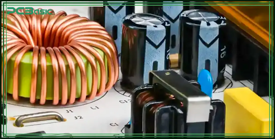
Replacing a faulty capacitor is one of the simplest yet effective repairs that you can make to solve electronics problems and not to purchase new devices.
Just follow these steps, and your gadget will be up and running in no time.
The first thing that might make you think something is wrong with your device is if it ceases to function or behaves abnormally. A dim screen, screen brightness that goes on and off, and other unusual operations may indicate a bad capacitor.
In some cases, it is necessary to discharge any stored electricity before proceeding with the replacement to avoid accidents. Switch off the device, disconnect it from the power source, and then wait a few minutes before proceeding. Better safe than sorry!
To get the job done, you'll need:
· Screwdriver for removing casings
· Soldering iron
· Solder wick or copper braid for removing old solder
· Replacement capacitor, preferably of the same value as the original capacitor
· Safety glasses (soldiering involves the production of sparks and fumes).
First, unscrew or remove any cover pieces to expose the circuit board inside the device. The most common signs of a problem are bulging, leakage, or cracks in the capacitors – those are typically the causes of the problems. Sometimes the suspicious cap will be apparent, at other times, you have to look at it closely or check the components to identify the faulty one.
Preheat your soldering iron and place the desoldering wick or braid on one of the capacitor's legs and then apply the heat of the soldering iron on top of it to suck out the solder. Do the same for the other lead and carefully remove the capacitor from the board. Clean the pads with the help of the wick to take out the remaining solder.
Before soldering in the replacement:
1. Trim its leads so they're the same length and sit evenly with the board.
2. Slide the new cap's wires into the vacant solder pads.
3. Melt new solder into each one while holding the lead firmly so it stays in place.
4. Check that the capacitor sits straight and the solder joints are good before moving on.
With the new capacitor secured, carefully replace any case pieces or covers you removed. Reconnecting the battery or power adapter should bring your gadget back to working order. Power it on to test! If it powers up without issues, your repair was a success.
Choosing the suitable capacitor for your circuit board can seem daunting because of the various types, specifications, and considerations. However, with some knowledge of the key factors, you can select capacitors that best meet your design needs.
Let's break down the important attributes to examine when choosing PCB capacitors.
The core function of a capacitor is to store electric charge. The capacitance value determines how much charge can be stored for a potential difference. This is crucial as it directly impacts the capacitor's ability to perform its intended task in the circuit.
The minimum capacitance required depends on factors like the operating frequency and load demands. Selecting a capacitor rated at least 20% higher than the calculated minimum is good practice to allow for tolerances and component variations over time. Oversizing too much can lead to unnecessary costs, however.
Always cross-check the capacitance called out in your schematic versus the component ratings. Pay attention to units too - a capacitor labeled in microfarads (μF) won't do the job of one in picofarads (pF). Proper capacitance selection ensures your circuit functions as designed.
Ideally, choose a capacitor with a working voltage rating at least 50% higher than the maximum voltage it will experience in the circuit. This protects the capacitor from voltage stress that could cause dielectric breakdown over time.
It's also crucial to account for voltage transients and spikes in your power lines. These occasional high potentials can damage parts with insufficient breakdown voltage tolerance. Consider expected operating conditions and safety factors when verifying voltage specifications.
The optimal capacitor type depends on factors like required capacitance, operating voltages, frequency performance needs, temperature range, and physical constraints.
Ceramic and film capacitors offer tight tolerances but lower capacitance than electrolytics. Electrolytics provide high capacitance densities at moderate costs but have larger physical sizes.
For high frequencies, look at materials with lower equivalent series resistance like polymer, mica or silvered mica dielectrics. Whereas power filtering calls for capacitors rated to handle surges and ripple currents.
Always consult datasheets for detailed electrical characteristics and understand limitations to select the capacitor variety most suited to your application needs.
The equivalent series resistance (ESR) of a capacitor indicates its losses due to internal resistance. Lower ESR capacitors are more efficient, generating less heat dissipation under load.
ESR becomes particularly important at high frequencies, contributing to more inductive reactance. Its effects on circuit performance need accounting too. Ceramic and film capacitors generally have the lowest ESR.
As operating frequencies increase and pass the capacitor's self-resonant point, ESR shoots up, deteriorating its effectiveness. Component data sheets provide typical ESR versus frequency plots to help with selection. Lower ESR options are preferred in circuits with tight regulation requirements.
Component real estate is valuable on tightly packed PCBs. Consider footprint constraints, especially for surface mount designs. Physical envelope and termination styles also limit mounting options.
Radial leaded capacitors require through-hole installation, whereas chips and multilayer surface mount types offer compact solutions. Special geometric capacitors fit confined spaces.
Thermal derating may require larger cases for high ripple current or temperature-rated parts. Coupling and decoupling multiple capacitors aids power dissipation too. Ensure terminal arrangements, lead clearances, and mounting configurations match your design methodology.
Capacitance tolerance is the allowable variation from the nominal value due to manufacturing spreads and operating conditions like temperature, voltage, and frequency. Different applications require different tolerance levels.
Precise timing, filtering, or resonant circuits may need tight ±1% tolerances for stability, whereas a broader ±10-20% range works well for decoupling multiples. Tighter specs increase costs without significant performance benefits in non-critical uses.
Always verify the tolerance band matches your design's sensitivity to capacitance deviations. Components outside tolerance yield could cause issues downstream.
Factors impacting long-term reliability include thermal stress, operating voltages, ripple currents, and frequency of operation. Electrolytic types typically last 2,000 hours at rated temperature versus 100,000 hours for film/ceramic dielectrics.
Derating capacitor specifications based on your temperature extremes and ripple currents ensures components live out their expected lifespan. Use manufacturer data for accelerated life tests simulating worst-case conditions.
Mission-critical or safety systems demand ultra-stable designs. Consider redundant backups, space-grade/militarized grades offering longer 5-10 year lifetimes over commercial grade parts. Prototype regularly to catch early life failures too.
Cost optimization is an important design metric, especially for high-volume production. However, pursuing the absolute lowest cost parts can backfire if they fail application requirements or field reliability testing down the line.
Compare total lifetime ownership expenses factoring in reliability across different capacitor types. While premium components carry higher unit costs, their durability may offset repeated replacement and long-term downtime expenses.
Evaluate cost-performance tradeoffs closely based on your production and support scenarios. Small cost premiums for militarized or industrial grades can also give considerable peace of mind for mission-critical applications.
Capacitor datasheets are the bibles detailing electrical characteristics, design guidance, and testing conditions. Ensure you source components from reputable manufacturers with published specifications that match your operating environment.
Consult application notes for design recommendations tailored to your circuit functions. Reputable manufacturers also stand behind the quality of their parts with warranties and failure analysis support.
Deviations from recommended operating specs or improper handling can void warranties, leading to poor reliability and wasted rework costs. Standardized testing procedures ensure consistent performance assessments. Stay within stated operating ratings for best lifetime expectancy.
As we have seen in this article, capacitors play a very important role in the smooth running of any electric device. Apart from storing and releasing electric charges, they also regulate the amount of voltage and filter out current noise.
There are many factors that you must consider when choosing the suitable capacitor for your project. Failure to do this may damage your device or even pose a danger to you. With that in mind, you must match the exact capacitor specifications to your circuit board design to achieve optimum performance.
As a market leader in PCB and PCBA design and assembly, PCBasic can assist you get the right design for your circuit board capacitors. We offer full-service PCBA solutions, including prototype assembly and high-volume manufacturing.
Visit our website for online quotes and to discuss your circuit board project needs. Our team of experts can help turn your design concept into a finished, tested product.

Assembly Enquiry
Instant Quote
Phone contact

+86-755-27218592
In addition, we've prepared a Help Center. We recommend checking it before reaching out, as your question and its answer may already be clearly explained there.
Wechat Support

In addition, we've prepared a Help Center. We recommend checking it before reaching out, as your question and its answer may already be clearly explained there.
WhatsApp Support

In addition, we've prepared a Help Center. We recommend checking it before reaching out, as your question and its answer may already be clearly explained there.
