
Global high-mix volume high-speed PCBA manufacturer
9:00 -18:00, Mon. - Fri. (GMT+8)
9:00 -12:00, Sat. (GMT+8)
(Except Chinese public holidays)





HomePage > Blog > Knowledge Base > Power Module PCB Assembly: What Makes a Reliable Build?
1. What Makes Power Module PCB Assembly Different?
2. Reliable Assembly Starts with the Right Components
3. Small Assembly Details Can Affect Everyday Performance
4. How Do You Know the Finished Module Is Ready?
This is also why power module PCB assembly is worth paying attention to. The drawings specify the positions and connection methods of the components, but in actual production, the problem of how to assemble them properly needs to be solved. For example, the large inductor and the small surface mount component next to it may have different heating conditions during soldering. Having the components in place is not the same as completing the assembly work.
Whether you are working on a DC-DC or AC-DC power module, ultimately, you need to see if it can work properly when installed in the equipment. Let's start from the details of the actual assembly and see which aspects need attention and how to confirm that the finished product meets the requirements before delivery.
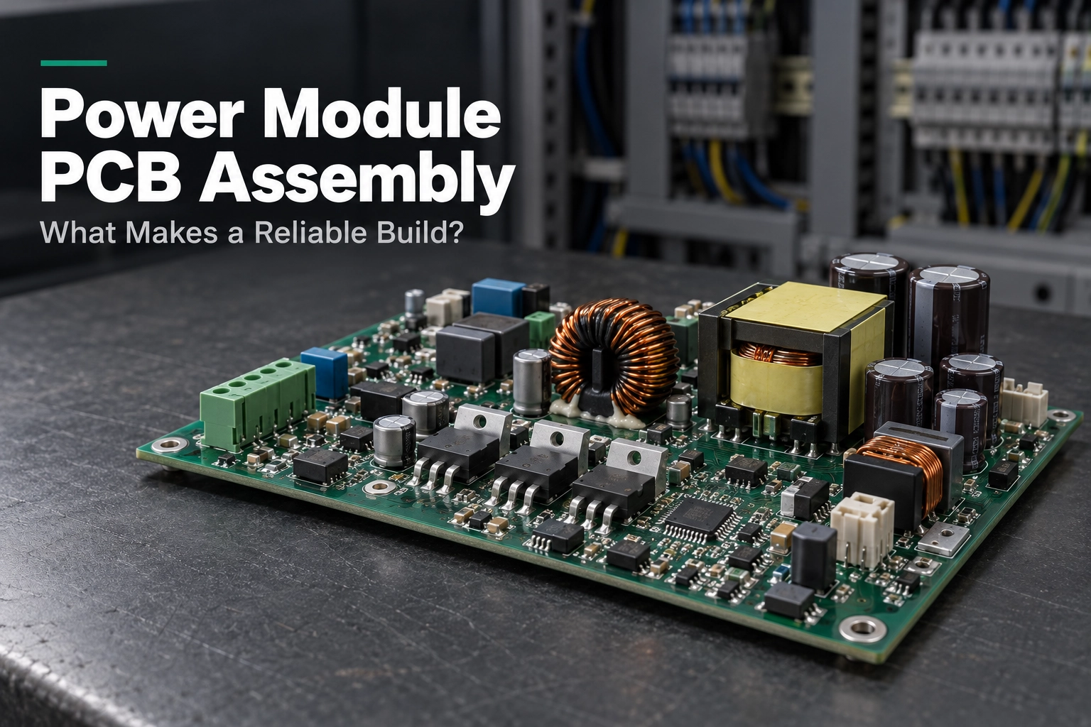
Carefully looking at a power module circuit board, you may notice that the small control components are adjacent to much larger inductors, capacitors or connectors. These components have different purposes and usually require different assembly methods. Small ICs are typically assembled using surface mount technology, while some larger components are connected by through-hole connections and may require additional support. How to assemble these components on the same circuit board is a key issue that needs to be considered in power module PCB assembly.
In addition, the electrical and thermal requirements of the circuit board also affect the assembly method. The role of the copper areas is not only to carry current and dissipate heat during the operation of the device. During production process, they can also take heat away from the solder joints. Therefore, when choosing and adjusting the soldering process, we need to consider the impact of these copper areas on the heating of the solder joints. If a heat sink needs to be installed, we also need to pay attention to its contact with the device and whether it can be correctly installed in the closure. The power module PCBA requires both reliable electrical connections and a correctly installed heat dissipation structure.
The focus of different products also varies. In compact DC-DC converter PCB assembly, the limited board surface space may increase the difficulty of component mounting and solder joint inspection. While for the AC-DC power supply PCB assembly powered by mains electricity, it is necessary to pay attention to the specified insulation and electrical spacing requirements. There is no one structure that suits all modules. Which specific details need to be paid attention to also depends on the product design and the actual operating conditions.
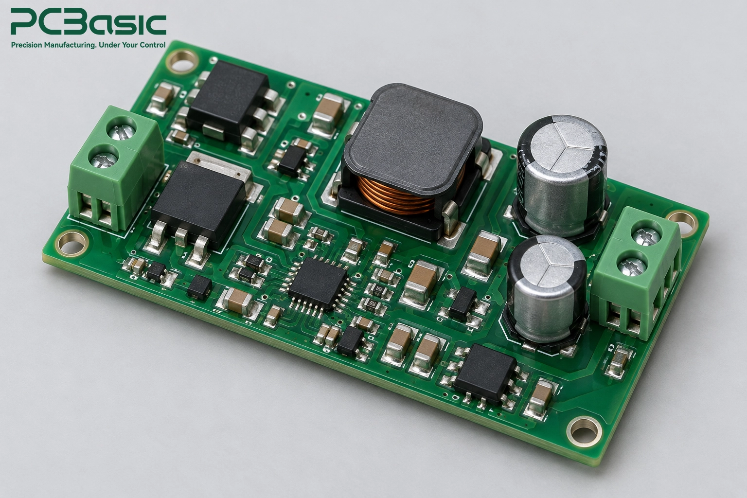
In power module PCB assembly, we must first ensure that the components and board materials meet the design and operating requirements. A component may be perfectly compatible with the circuit board, but still not suitable for practical use. Checking the approved specifications before production can help us reduce subsequent problems caused by the inappropriate substitute materials.
The power semiconductors in the power module PCBAs are responsible for switching and rectification, while capacitors and magnetic components are used for filtering and energy transmission. The specific components used depend on the circuit. For example, small DC-DC modules and large industrial converters may have significant differences in their component usage.
For power supply PCB assembly, we cannot simply judge whether two components can be replaced based on their appearance. Two capacitors with the same capacitance may have different rated ripple current or service life. The same applies to inductors. Even though the replacement model can be installed on the same pads, the rated saturation current of the replacement model may be lower. These differences may affect the performance of the module under load.
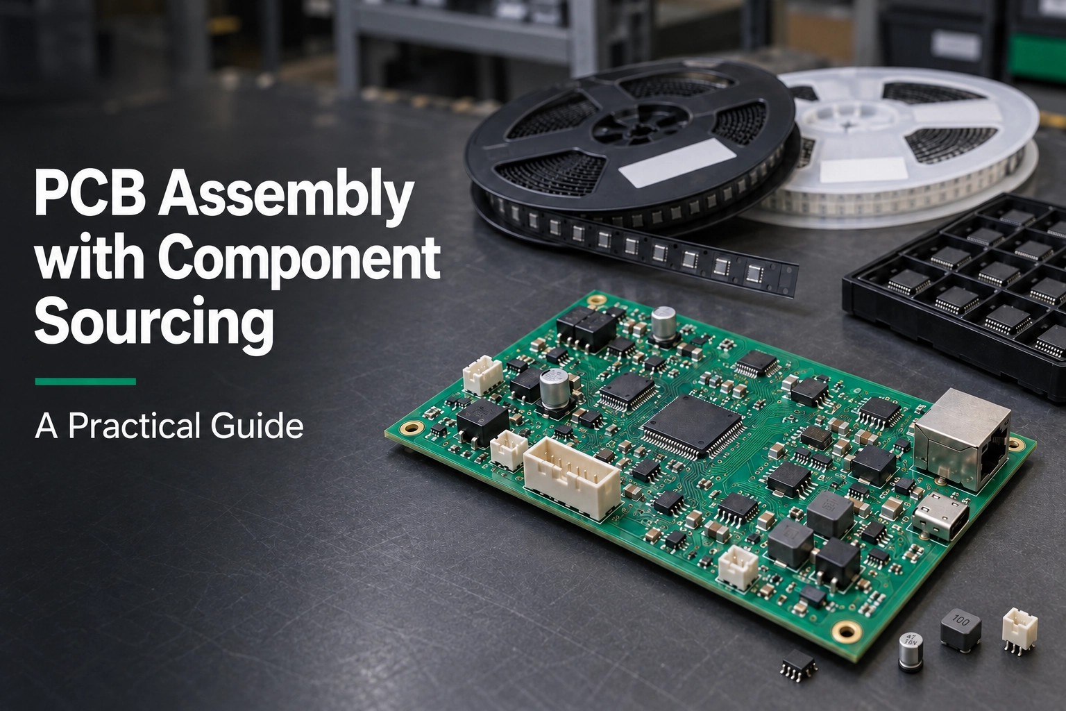
Therefore, in the BOM (Bill of Materials), the approved manufacturer part numbers and acceptable substitutes should be clearly stated. When the original part is out of stock, we cannot directly replace it with a seemingly similar component. We need to first have it reviewed by the engineers. PCBasic provides component sourcing and incoming inspection services, helping to verify whether the supplied components meet the BOM requirements of the power module PCBA.
The bare PCB also needs to comply with the manufacturing specifications. FR-4 is very common in power products. Some designs may choose metal substrates or ceramic substrates based on thermal and electrical requirements. Each has its applicable conditions and cannot be replaced with each other without review.
The copper thickness is important, but it cannot solely determine the current-carrying capacity. The trace width, the position of the layer, and the allowable temperature rise also affect the design. Therefore, not every power supply PCBA needs heavy copper. For AC-DC power supply PCB assembly, we also need to pay attention to the insulation performance specified by the board materials.

The electrical rated parameters meet the requirements, but the size may still be inappropriate. For example, an alternative capacitor may meet the electrical requirements, but it is too tall and cannot fit into the housing. Larger inductors or transformers may also require additional support to avoid excessive stress on the solder joints.
The space for compact DC-DC converter PCB assembly is usually limited. Differences in size are more likely to affect installation. It is much easier to check the component dimensions and the specified mounting method before soldering than to remove and adjust them after assembly.
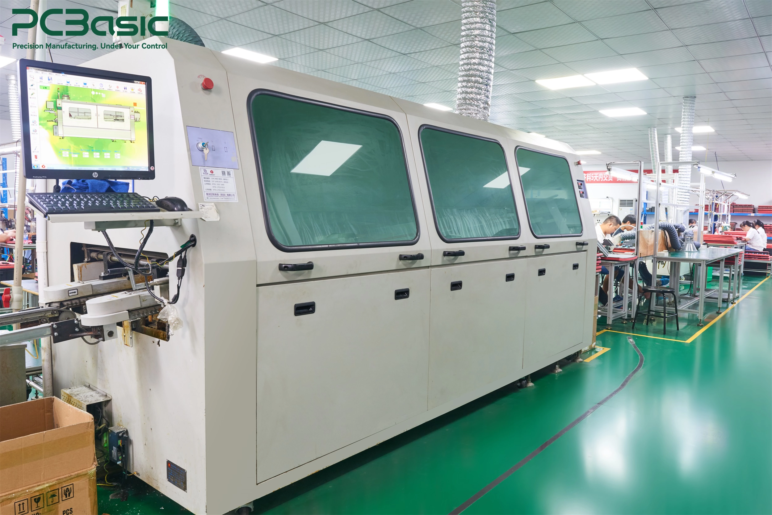
The right components have been selected, but it is also important how to solder and assemble them. In power module PCB assembly, the solder joints at the bottom of the components or the shifted thermal pads are not easily detectable from the surface. We need to check these details during the assembly.
The heating speed of components on the same board may vary. If the solder joints are not heated sufficiently, can we simply increase the furnace temperature? Not exactly. Some components may have overheated, while other areas have not yet reached the appropriate soldering conditions.
Therefore, we need to measure the reflow soldering profile using a template and confirm the amount of solder paste and the size of the stencil openings to match the solder pads. The hidden solder joints at the bottom of the components can be inspected using X-Ray according to the agreed standards.
In AC-DC power supply PCB assembly, through-hole components should be selected for soldering methods based on the layout and process requirements. During the inspection process, in addition to checking the appearance, it is also necessary to confirm whether the solder filling in the holes and the installation of the components meet the requirements.
If the power supply PCBA requires the installation of a cooling component, we should focus on checking:
• Contact condition: Is the heatsink installed flatly? Has the thermal pad shifted or folded?
• Fixation and insulation: Are the fasteners installed as per the specifications? Are the insulating parts missing or displaced?
• Airflow: Are the wires arranged as per the drawing? Are there any obstructions to the intended airflow path?
The spacing shown in the drawings meets the requirements. However, it is still necessary to confirm it after assembly. Long component pins or wires deviating from the route may cause the conductors to be too close to each other.
For power module PCBA with clear isolation requirements, we need to check the creepage distance and electrical spacing of the finished product against the assembly drawing, and include related heat sinks and installation hardware in the inspection scope.
After completing power module PCB assembly, we need to conduct inspections and tests to confirm whether the finished boards meet the requirements. The specific items to be checked and the criteria for determining qualification should be clearly defined with the customer before production begins.
Before testing the power supply PCBA, we need to clearly define the testing conditions and acceptance limits, and then arrange the checks according to the product requirements:
|
Check items |
What to look for |
|
Output voltage |
Whether it remains within the specified range under the specified load |
|
Ripple and noise |
Whether it exceeds the limit |
|
Efficiency and temperature rise |
Whether the loss and heat generation meet the requirements |
|
Start-up and load variation |
Whether the module can respond as required |
|
Protection functions |
Whether it works as expected |
The testing methods should also be consistent. The connection of the probe and the settings of the oscilloscope will affect the ripple readings, while the airflow and cooling configuration will influence the temperature results. Due to different conditions, the data cannot be directly compared.
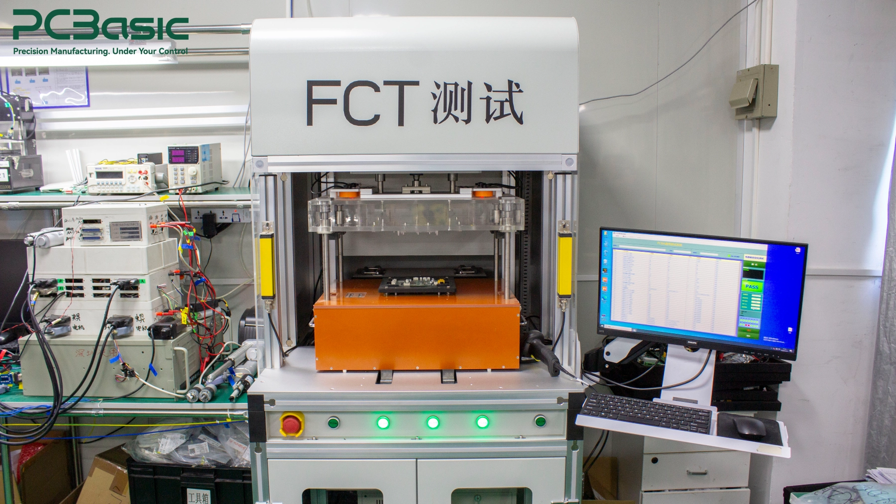
AOI, X-Ray and ICT can detect different types of assembly or electrical issues, but they cannot replace functional testing. DC-DC converter PCB assembly needs to be verified for output performance as per the plan; AC-DC power supply PCB assembly may also require insulation-related tests.
Do all boards need to undergo burn-in or temperature cycling? Not necessarily. It is necessary to distinguish between individual unit production inspection, sampling testing and product verification. EMC testing may also need to be conducted after the module is installed in the finished equipment.
PCBasic offers AOI, X-Ray, ICT and PCBA functional testing, and can also arrange burn-in, temperature cycling, and vibration tests according to project requirements. We will confirm with you the requirements for various inspections and tests before production, and associate the results with the corresponding power module PCBA or batch, to facilitate delivery verification and subsequent traceability.

For a reliable power module PCB assembly, we cannot merely focus on whether the components are installed correctly and whether the solder joints look good. We also need to consider the performance of the module after it is installed in the equipment. Before delivery, we check the assembly details against the product requirements and confirm through testing whether the finished module is qualified.
Are you preparing the power module PCB assembly project? Contact PCBasic to discuss where your module will be used and what requirements it needs to meet. We can jointly identify the points that need attention during the assembly process and the inspections and tests that should be done before delivery.
Q1: What Is the Difference Between a Power Module PCB and a Power Module PCBA?
A power module PCB is the bare circuit board, containing conductive tracks, pads, and other board features. A power module PCBA has components mounted and connected to it. It may still require testing, mechanical integration, or other finishing steps before delivery.
Q2: Can Power Modules Use Both SMT and Through-Hole Components?
Yes. Power module PCB assembly often combines surface-mounted control and power components with through-hole transformers, terminals, or capacitors. The combination depends on the approved design. Manufacturers select the assembly sequence and soldering methods to suit the components and board.
Q3: Does Every Power Module Need Burn-In Testing?
No. Burn-in is an additional screening process used when the product requirements or agreed quality plan call for it. For power supply PCBA, its conditions and duration should be defined. Burn-in complements appropriate inspection and functional testing; it does not replace them.
Assembly Enquiry
Instant Quote

Phone contact

+86-755-27218592
In addition, we've prepared a Help Center. We recommend checking it before reaching out, as your question and its answer may already be clearly explained there.
Wechat Support

In addition, we've prepared a Help Center. We recommend checking it before reaching out, as your question and its answer may already be clearly explained there.
WhatsApp Support

In addition, we've prepared a Help Center. We recommend checking it before reaching out, as your question and its answer may already be clearly explained there.
