
Global high-mix volume high-speed PCBA manufacturer
9:00 -18:00, Mon. - Fri. (GMT+8)
9:00 -12:00, Sat. (GMT+8)
(Except Chinese public holidays)





HomePage > Blog > Knowledge Base > Robotic Control Board Assembly: What to Test Beyond Power-On
1. Define the Robotic Control Board Assembly Scope
2. Separate Assembly Inspection from Control Function Testing
3. Define Power, Feedback, Communication, and Load Test Conditions
4. How PCBasic Supports Robotic Control Board Assembly
In robotics hardware, basic power-on only confirms that the monitored rails, such as 3.3 V, 5 V, and 12 V, reach their expected voltages under the initial test conditions. It tells you nothing about whether your gate drivers survive high dv/dt switching transients, whether your differential encoder receivers reject noise coupled from the motor phases, or whether your controller maintains deterministic loop timing when multi axes operate at their specified peak loads.
For hardware engineers and electronics buyers sourcing robotic control board assembly, bridging the gap between "it turns on" and "it performs its motion-control functions as specified" requires a structured post-assembly verification strategy. Defining clear functional test boundaries before production reduces the risk of costly field returns, stalled system integration, and disputes between firmware teams and contract manufacturers.
Unlike standard consumer or static industrial controllers, a robot mainboard often sits at the intersection of high-speed digital processing, sensitive analog sensing, and noisy power switching. Even when high-power motor inverters live on separate joint-level driver boards, the central robot controller PCB assembly can integrate dense mixed-signal subsystems that demand tight process control during manufacturing.
When scoping robotics PCB assembly with a contract manufacturer, engineering and procurement teams must account for the physical and electrical realities of the board architecture:
• Compute and Real-Time Control Core: Multi-core processors, FPGAs, or real-time MCUs (such as those in the STM32H7 or TI C2000 families), some of which come in fine-pitch BGA packages and require package-specific reflow profiles and moisture sensitivity level (MSL) handling.
• High-Density Interconnects and Mechanical Retention: Board-to-board mezzanines connectors, locking wire-to-board headers (e.g., from JST, Molex, or Hirose), and shielded M8/M12 industrial connectors that must withstand the specified vibration conditions without intermittent contact or solder-joint cracking.
• Isolated Gate Drive and Auxiliary Power Stages: Integrated DC/DC converters, digital isolators, and local MOSFET half-bridges for brakes, grippers, or cooling fans where applicable creepage and clearance requirements and thermal pad soldering quality affect field reliability.
• Deterministic Fieldbus Interfaces: CAN FD (with multiple channels where required), EtherCAT (with PHYs and magnetics as required by the physical interface), RS-485, and industrial Ethernet ports that rely on interface-specific impedance and termination requirements.
• Sensor Acquisition Front-Ends: Differential quadrature encoder inputs, SPI/SSI absolute encoder ports, IMU sensor clusters, and current-sense amplifiers operating next to high-current switching paths.
Because these subsystems interact tightly, treating robot PCB assembly as a commodity "stuff-and-solder" transaction can leave critical failure modes undetected until final robot commissioning.

A frequent source of friction between engineering teams and suppliers is the assumption that structural inspection equals functional readiness. AOI and X-ray inspection assess physical workmanship—with AOI checking visible features such as component presence and orientation, and X-ray checking for indications of hidden solder bridges or excessive BGA voiding. Functional testing (FCT) and end-of-line control validation verify how the assembled circuit behaves under specified electrical stimuli.
The comparison below shows what each verification stage checks and which issues require further testing:
Verification
Stage
Primary
Inspection Method
What
It Checks
What
It Misses
Pre-Reflow & Solder Paste
3D SPI
Paste volume,
alignment, and bridging.
Incorrect
component values and electrical faults.
Post-Reflow Structural
3D AOI & X-Ray
AOI: component
placement and visible solder defects.
Firmware and
dynamic electrical faults.
Electrical Test
Flying Probe or Bed-of-Nails ICT
Opens, shorts,
and selected component values.
Noise coupling
and voltage droop under load.
Bench Power-On
Programmable PSU & DMM
Input current,
rail voltages, and MCU startup indication, if available.
PWM timing,
encoder dropouts, and bus errors under load.
Functional Testing (FCT)
Hardware-in-the-Loop and/or Load Rig, as
required
PWM timing,
feedback, bus communication, and thermal response under load, as specified.
Long-term
mechanical fatigue.
X-ray: hidden solder bridges and voiding.
Separating these gates in your manufacturing test plan gives procurement clear acceptance criteria and gives test engineers actionable fault isolation. If a board fails AOI, the SMT line confirms the defect and investigates the relevant process step before making adjustments. If a board passes AOI and power-on but fails FCT on Axis 3 current feedback, technicians start by checking the current-sense signal path, including the shunt amplifier and its connections.
To move beyond basic power-on verification, your test specification should define measurable pass/fail limits across five operational domains. Providing these parameters to your robot PCB assembly manufacturer helps reduce ambiguity during test fixture development.
Static voltage checks on an unloaded board can miss weak solder joints on inductors, poorly wetted thermal pads under buck controllers, and out-of-spec capacitor ESR.
• Quiescent vs. Active Current Draw: Measure input current at the main logic supply input (e.g., 24 V or 48 V) before and after firmware boot to flag abnormal current draw that may indicate leaky ESD diodes or partially shorted ceramic capacitors.
• Load-Step Transient Testing: Apply fast current steps (e.g., 0.5 A to 3 A at 1 A/µs, where appropriate for the rail rating) on auxiliary 5 V and 3.3 V rails using an electronic load to verify that the rail voltage stays within its specified transient limits and switching ripple remains below the specified limit.
• Reverse-Polarity Protection and E-Stop/STO Response: Verify that the input protection behaves as specified under reverse polarity and that an E-stop command or Safe Torque Off (STO) input produces the specified response within the applicable time limit.
Whether the control board drives small motors directly or outputs PWM signals to external servo amplifiers, signal fidelity affects motion smoothness and power stage reliability.
• PWM Frequency, Duty Cycle, and Dead-Time: Capture complementary high-side and low-side PWM channels simultaneously on an oscilloscope or high-speed counter to confirm the specified dead time and check for overlap in the PWM commands.
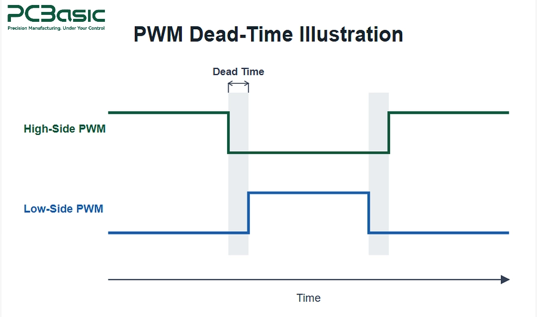
• Gate Drive Edge Rates and Ringing: Measure rise/fall times and voltage overshoot at the MOSFET gates relative to their respective sources, or at the differential line driver outputs as applicable. Excessive ringing warrants checking the measurement setup, layout parasitics, and gate-drive components.
• Brake and Solenoid Driver Actuation: Switch inductive holding-brake outputs into real or simulated inductive loads to verify the specified flyback clamping and, where implemented, peak-and-hold current control.
A robot's positioning accuracy is affected by the noise floor and calibration integrity of its feedback front-end.
• Quadrature and Absolute Encoder Simulation: Inject calibrated A/B/Z differential pulse trains at the specified test rates or simulate SSI/BiSS-C encoder responses to the controller’s clock to verify correct decoding and check for missed counts or frame errors over a timed capture window.
• Current-Sense Amplifier Offset and Gain: Feed known millivolt test signals across shunt inputs (or inject calibrated currents) at zero and across multiple specified input levels to verify zero-current offset voltage, gain accuracy, and linearity across all motor phases.
• Analog and IMU Sanity Checks: Read onboard temperature sensors, sample the bus-voltage divider outputs through the ADC, and read 6-axis IMU registers over SPI or I2C, confirming that measured noise stays within the specified test limits when nearby switching regulators are active.
Communication dropouts in a multi-axis robot can trigger a fault or stop response, depending on the controller configuration and timeout settings. Testing ports in isolation at room temperature can miss marginal transceiver assembly defects.
• Simultaneous Multi-Bus Traffic: Run protocol-appropriate stress traffic across EtherCAT, CAN-FD, and RS-485 ports simultaneously while toggling high-current auxiliary outputs to expose communication errors that may indicate ground bounce or poorly soldered common-mode chokes.
• Bus Termination and Bias Verification: Measure termination resistance across the applicable differential pairs and idle bias or common-mode voltages where specified to catch missing or incorrect termination and bias components.
For control boards integrating onboard power stages, high-current busbars, or brake drivers, thermal profiling under sustained load can reveal anomalies associated with mechanical and solder defects that look normal during an unloaded inspection.
• Kelvin Voltage Drop Checks: Measure millivolt drops across high-current connectors, fuses, and shunt paths under rated continuous current to detect excessive connection resistance that may result from under-filled through-hole barrels or improperly torqued terminal blocks.
• IR Thermal Stabilization: Monitor key power ICs, MOSFETs, and magnetic components with an infrared camera during a defined run under load—checking that measured surface temperatures remain within the specified limits and flagging localized hotspots for further investigation.

Executing multi-stage inspection alongside customized functional testing requires a contract manufacturer with the engineering and test capabilities to support high-mix builds. PCBasic supports hardware engineers and procurement teams with integrated turnkey robotics PCB assembly workflows designed to catch defects before boards reach your integration lab.
Robotic controllers rely on precision op-amps, isolated gate drivers, and automotive- or industrial-grade MCUs, and counterfeit or out-of-spec parts can cause subtle field failures. PCBasic enforces incoming quality control (IQC) using applicable LCR checks and BOM verification, with MES-based component traceability and sourcing according to project requirements. PCBasic lists ISO 9001, IATF 16949, and ISO 13485 among its quality management system certifications.
Equipped with FUJI NXT III and AIMEX III placement lines, 10/12-zone lead-free reflow ovens, and selective soldering and wave soldering capabilities for ruggedized through-hole connectors, PCBasic handles dense BGA layouts alongside heavy-duty power headers.
PCBasic uses 3D SPI for solder paste inspection and 3D AOI for SMT assembly inspection, with targeted X-ray inspection available as specified to check hidden joints for indications such as BGA solder bridges or voiding beneath QFN thermal pads.
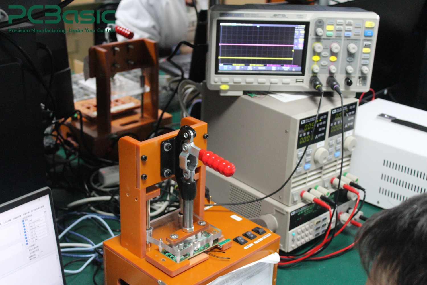
Beyond standard assembly inspection, PCBasic offers dedicated in-house functional testing and burn-in facilities. Engineering teams can supply custom test jigs, test scripts, or firmware flashing and load-test procedures so each robotic control board assembly undergoes agreed power-rail, communication, and loaded thermal checks before shipment.
Passing a basic power-on check is only the starting line for a robotic controller. True production readiness demands verifying how the assembled hardware performs when PWM signals switch at the specified frequency, encoder signals traverse noisy interconnects, fieldbuses carry the specified traffic load, and power stages heat up under sustained load.
By separating structural assembly inspection from functional control testing—and documenting clear electrical pass/fail criteria up front—engineering and procurement teams can reduce the risk of costly integration bottlenecks. When preparing your next build, sharing your Gerber files, BOM, assembly drawings, and functional test specifications early allows your manufacturing partner to identify DFM risks and execute the agreed end-of-line testing from prototype through production.
Q1: What documentation should we send a manufacturer to set up functional testing for a robotic control board?
Along with Gerber files, pick-and-place data, and the BOM, provide a functional test procedure. Include test points, required firmware files, test conditions, and pass/fail limits for power, communication, and outputs.
Q2: Why do boards pass AOI and X-ray inspection yet fail during motor or actuator bring-up?
AOI and X-ray check assembly workmanship. Problems such as encoder dropouts caused by motor switching noise may only appear when the board drives an actuator or runs on a representative test rig.
Q3: Should firmware flashing happen before or after functional testing during assembly?
If the test requires dedicated firmware, flash it after verifying the power rails and before running FCT. If production firmware is flashed afterward, verify its version and confirm that the board boots correctly.
Q4: How can procurement balance test coverage with assembly cost for low-to-medium volume robotics builds?
For prototypes and pilot runs, combine AOI, targeted X-ray, and a reusable functional test rig where they meet the required coverage. Consider a custom bed-of-nails ICT fixture when the required coverage and expected production volume justify the cost.
Assembly Enquiry
Instant Quote


Phone contact

+86-755-27218592
In addition, we've prepared a Help Center. We recommend checking it before reaching out, as your question and its answer may already be clearly explained there.
Wechat Support

In addition, we've prepared a Help Center. We recommend checking it before reaching out, as your question and its answer may already be clearly explained there.
WhatsApp Support

In addition, we've prepared a Help Center. We recommend checking it before reaching out, as your question and its answer may already be clearly explained there.
