Global high-mix volume high-speed Shenzhen PCBA manufacturer

Ru
9:00 -18:00, Mon. - Fri. (GMT+8)
9:00 -12:00, Sat. (GMT+8)
(Except Chinese public holidays)


Global high-mix volume high-speed Shenzhen PCBA manufacturer

Ru
9:00 -18:00, Mon. - Fri. (GMT+8)
9:00 -12:00, Sat. (GMT+8)
(Except Chinese public holidays)


HomePage > Blog > Knowledge Base > PCB Relays: Working Principles and Design Guide
Safety is very important in consumer electronics. And you know, without a PCB, any electronic gadget won't work. Therefore, to control the current and protect available parts on a circuit board, PCB manufacturers use PCB relays. A PCB relay follows voltage and current patterns to break or establish the connection.
Now the question is, What is a PCB relay? How can a common reader understand its basic concepts? In this article, you will read everything. That is relevant to circuit board relays, their importance, and their types.

Printed circuit boards work as electromagnetic gadgets to control the current supply. It is directly mounted on circuit board assemblies to regulate the switching of loads. Consequently, it manages the higher voltage circuits through a lower power control signal.
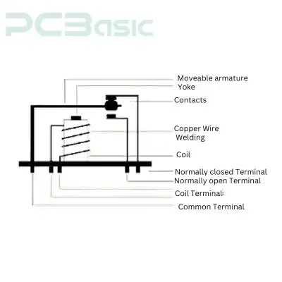
Relays are usually constructed with 5 terminal sorts. That includes the N/C (normally closed) and N/O (normally opened) terminals. The manufacturer attaches the electromagnetic components to PCB relays along the moveable metal arm.
A magnetic field is created on the board when the manufacturer passes the current on this metal arm. It enables the arm to move toward either the N/C terminal or the N/O terminal. This is a simple mechanism, though it can handle the high-voltage switching efficiently.
They eliminate the chances of high-voltage spikes in power systems. It is widely used in industrial sectors. That needs long-lasting attributes and reliable performance. For instance, machinery applications, power systems, automotive, and telecommunications equipment.

Consumer electronics require effective board assemblies to handle the voltage pressure. In accordance with this, PCB relays are one of the foremost reliable components. That helps in managing the current flow.
The relay of PCBs shows unique features. That can impact the performance of circuits. Consumers should select the best relays by weighing their features.
● Galvanic Isolation
● Compact Size
● High Durability
● Fast Switching
● Low Power Consumption
● Versatility
The relays for PCBs offer galvanic isolation features. You can utilize them to isolate the electric circuit or assemblies so that the current power supply can switch between low and high voltage. It helps in separating the circuit board's connectivity from the electric flow. Besides this, it reduces the chances of electric shock and damage. You can obtain safety measures for your project.
Electronic devices require compact components to save their valuable space. In this case, the PCB relays eliminate the need for extra spacing as they directly contend on the boards.
The heavy speed of electricity in extensive parts of machinery or other devices needs reliable switching boards. The PCB relays meet the criteria of reliability for consumers. The engineers preferred these relays to increase the durability of their projects. These relays help them control the mechanical stress issue and critical power systems.
Heavy machinery items and consumer electric gadgets sometimes require fast switching for rapid response. These relays are excellent choices to meet these criteria of high-speed switching.
The most common feature of PCB relays is that they do not need extra power. As we know, the moving arm of relays does not require any power when they are not operated.
PCB relays perform different functions across multiple applications. You can employ them in several mechanical parts, automotive vehicles, aircraft, and industrial components.
The varieties of PCB relays are easily available in the market. They work differently on distinct projects.
● Electromechanical Relays (EMRs)
● Solid-State Relays (SSRs)
● Reed Relays
● Latching Relays
● PCB Power Relays
Electromechanical relay is the most common type. It includes the electromagnet and mechanical metal arm. The manufacturer provides the power supply to produce the magnetic contacts. Following this, the armature switches the current flow between open and closed terminals. EMRs offer reliability and durability attributes. That helps maintain the large load of power systems.
Solid-state relays include semiconductors to handle circuit loads instead of moving contacts.
This PCB relay provides rapid switching performances. It increases the longevity of products by offering good resistance to mechanical wear. However, in contrast to EMRs, it is expensive.
You will find the reed relays built with a pair of magnetic reeds. These reeds are enclosed in a glass tube. The manufacturers transfer the current flow to create magnetic surrounds on the boards. Then, all the reeds are secured to direct the current flow. If you are looking for extra-sensitive relays, then choose Reed relays. However, they are not suitable for heavy-load products.
Latching relays are a subtype of electromechanical relays. It is commonly chosen to save energy consumption because they do not require a continuous power supply. It only uses energy power to handle the current supplies.
The PCB power relays effectively control the high voltages of current loads. They handle the essential loading pressures in heavy-duty products. These relays are designed for power distribution systems, industrial fields, or heavy machinery.

The personnel should know the internal mechanism and working process of PCB relays. That will help them understand this part's importance in circuit boards. It contains the electromagnetic coil, set of terminals, and armature assemblies. That is constructed to transfer the current supply. They enable the boards to open or close the circuits.
PCB relays are designed to operate electrically for switching purposes. As we discussed earlier, they control the flow of current. Besides, its mechanical workability involves several steps:
● Electromagnet Activation
● Magnetic Field Creation
● Switching Action
● Return to Initial State
The manufacturers activate the electromagnet. They supply the low power. This current power energizes the coil.
When the current load is transferred through the coil, it creates a magnetic field. This field attracts the armature (metal arm) towards the opposite terminal.
A passing current triggers the moving part of the relay. This arm either comes into contact with the break (NC) or establishes a (NO) position for switching the circuit boards.
● NC (normally closed): in this position, the relay contact remains closed by default. It is activated by transferring the power into the relay.
● NO (normally open): this switching action remains open until the relay is activated. The makers close this contact by attaching the electric power supply.
After removing the control signal, the moving arm of the relay shifts to its initial state. In this way, the current flow is stopped to break the magnetic field.
The engineers design the relays of the PCB in a way that perfectly fits as a constituent part of the boards. They enhance the workability and performance of circuits. Nevertheless, the integration of relays with circuit board assembly includes:
● Mounting Style
● Electrical Connections
● Custom Configurations
You can integrate the PCB board relays using two main mounting styles. These methods are:
● Through-Hole Mounting (THT)
● Surface-Mount Technology (SMT)
The engineers put the relay pins into pre-drilled holes on PCB boards during through-hole mounting. They solder the pins on the copper surfaces of the board. This is a secure and effective technology. That helps in stabilizing the mechanical connections. The personnel find this method beneficial for heavy-duty applications.
Surface-Mount Technology (SMT)
In SMT, the relay pins are soldered to the surface of the copper plates on the PCB boards. This technique is suitable for constructing applications with lightweight components and in compact size.
The engineer connects the relays with other parts of the PCB boards. That makes the relays workable. They connect them through the conductive surfaces and pads on the board assemblies. Then, these tracks create the circuit path to interact with the relays with sensors. Additionally, they form the contact between relays, power supplies, and output gadgets.
You can manage or connect the PCB relays on boards according to the design of the boards. These custom configurations help in controlling the various devices or board parts with a single power control. It is useful while creating complex electrical systems.

To design effective circuit boards, you should consider a few important factors.
Figure out the instructional design requirements of consumers. Choose the relays that easily meet the demands without losing the design functionality.
● Voltage and Current Ratings
● Load Type
● Switching Speed
● Size Constraints
● Power Consumption
● Environmental Factors
The voltage and current rates are the initial factors to consider. The improper selection of voltage load may interrupt the current flow and damage the relays.
The load can be of different types. That may involve resistive, inductive, or capacitive. Therefore, negligence in load selection may result in poor performance. For instance, the loads for heavy-duty parts need special relay capabilities.
Switching speed in relays can not be the same for all various types of applications. Some lower-load products need simple speed. However, heavy machinery, industrial components, and high-energy-consuming parts require quick response switching.
Size is an important factor when designing PCB relays. Some electric devices are constructed with compact-size relays to reduce space usage.
We cannot assemble the products by attaching random power relays. It is always recommended to choose relays with a lower energy consumption attribute so that the unnecessary energy drain can be eliminated.
The devices exposed to outdoor environments, heat pressure, or moisture need relays with good environmental safety ratings.
After considering the design, the manufacturers should focus on mounting techniques. Here, we provide some of the crucial tips. That can improve the reliability of relays:
● Use Proper Footprint
● Thermal Management
● Soldering Quality
● Clearance
● Mechanical Stress
The proper footprint can ease the process of mounting relays on circuit boards. It will enable secure attachment of the pins to the copper tracks.
The manufacturer uses heat dissipation techniques for heat-sensitive products. They can add heat sinks to avoid heat generation during the operation of relays.
Solder the relay pins accurately on the surface of the boards. This is so they do not interrupt current transmission and fail the power system performance.
During the through-hole mounting process, the engineer should clear the unwanted components to create stability in the mechanical properties of relays.
Do not apply excessive mechanical stress while mounting the relay pins. This may impact the other components and can damage the relays over time.
The design of PCB relays can be modified in any layout. However, the engineers should consider several basic elements. These elements are constructed with relay parts. It accommodates the functionality of circuits.
● Circuit Design
● PCB Layout Design
● PCB Fabrication
● Component Assembly
● Testing
● Coding
● Final Testing
The circuit design in Pcb relays depends on the voltage load of products. Prefer the control input that can handle a particular voltage. This could be a microcontroller or varying voltage.
Match the relay coil voltage with the control signal voltage. Also, remember to add the protection elements like a flyback diode or snubber circuit. That will prevent the chances of damage and shock.
Ask your engineers to prepare the appropriate layout of the PCB. The relay footprint should contain specific space for soldering the elements. The track width of the PCB is much enough to handle high-voltage currents smoothly.
Furthermore, the PCB layouts should include isolated barriers. These obstacles will separate the HV and low-voltage components. The placement of the relay should not be nearer to heat dissipation and sensitive elements so that they do not interrupt the other parts.
Collaborate with reliable manufacturers to fabricate the PCB relays. You can specify the tolerance requirements. That should include:
● Layer alignment to precisely attach multiple layers.
● Copper thickness can increase the durability of applications. Choose between 1 oz and 2 oz.
● Guide them on the minimum trace width and spacing of all circuit components.
● Through technology, annular ring size matters.
Assemble the relays on the circuit board using the THT or SMT mounting process. Automatic soldering is applied through hole mounting. Likewise, reflow soldering is used in the surface mount technique.
Forward the circuits under testing steps to check their functionality. Ensure all the necessary components are connected to the board. Perform the testing process using safety measures.
The software is written with coding if the PCB relays are constructed with microcontroller-driven systems. It controls the relay connections and is placed on the controller's GPIO pins.
Check the board's workability to forward it for inclusion in consumer applications. The circuit boards should pass all the tests. That may involve current flow, switches, mechanical wearability, high-pressure loads, etc.

● Automotive Systems
● Industrial Automation
● Telecommunications
● Power Systems
● Consumer Electronics
● Medical Devices
● Renewable Energy Systems
● Security Systems
● Home Automation
PCBS relays are used in automotive systems to handle simple to critical current loads. Its application includes headlight control, power windows, ignition systems, and fuel pumps.
The industrial application needs PCB relays to manage complex systems. It helps control high-pressure loads and offers precise operations. For example, motors, conveyors, and automated machinery
In telecommunications gadgets, relays transmit communication signals. The routers, modems, and signal distribution systems are the common applications. That uses PCB relays for seamless operations.
PCB relays regulate the power distribution and protection systems in transformers, circuit breakers, and other power control devices.
In washing machines, air conditioners, refrigerators, and all other household items incorporate PCB relays. They control the power and provide safety in motors, heating elements, and compressors.
Medical devices use PCB relays for accurate performance and patient safety. Diagnostic equipment, monitors, and automated laboratory systems are examples.
Manufacturers place relays in the circuit boards to control the current spikes and protect sensitive parts of renewable energy systems. These parts are inverters, battery charging systems, and power grids.
These relays are widely used in alarms, surveillance equipment, cameras, and door locks. It handles the critical application systems.
PCB relays are more satisfactory for switching low to high powers in home automation devices. It improves the automatic operation of lighting, HVAC systems, and home appliances.
The voltage flow, either low or high, can be handled through Pcb Relays. These relays improve product performance and provide secure operations. It is a simple technique for switching the current supply between NO and NC. There are various features and types of PCB relays. Choose wisely while designing or fabricating your own PCB relays.

Assembly Enquiry
Instant Quote