Have you ever experienced the frustration of your electronic devices intermittently failing? Then, you might be dealing with "cold solder joints."
According to recent studies, almost 70% of electronic failures result from inadequate soldering. Keeping the stats in mind, we assume you're also suffering from the same and searching for a simple solution. So, let's dive deeper into the topic to learn more about it.
What is a Cold Solder Joint?
A "cold solder joint" is simply a solder that doesn't melt all the way through to create a perfect joint. In a cold solder joint, the solder doesn't form a strong and reliable connection between the components or leads it is meant to join. This lack of proper bonding can lead to various issues, including increased electrical resistance, intermittent functionality, and a higher likelihood of component failure.
Some variables that could lead to cold solder junctions are:
● Inadequate solder wetting, reflow, or melting of joint.
● Vibrations or other disturbances while the solder cools.
● The flux prematurely breaks down when the process temperature is too high.
● Insufficient wetting of solder junctions arises when the process temperature is too low.
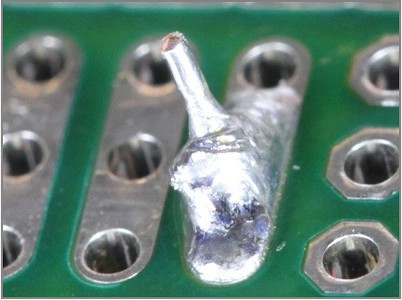
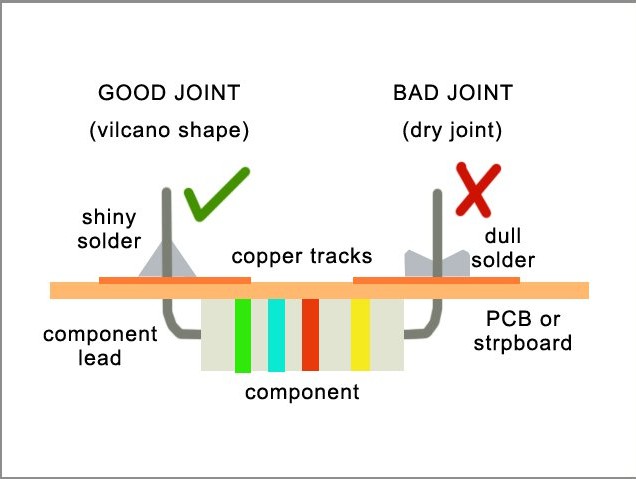
Common characteristics of cold solder joints include a dull and grainy appearance, as opposed to the smooth and shiny finish of a well-formed joint. These joints are often weaker mechanically and electrically and may not provide the necessary conductivity for the electrical components to function optimally.
You can identify the cold solder joint with a magnifying lens. Another method is to move the soldered component to check for a cold solder joint; if the joint is weak, the component will move a little.
Different Types of Cold Solder Joints
Now that you know what a cold solder joint is, let's look at some of its types.
1. Distributed Cold Joint
A distributed cold solder joint refers to a situation where inadequate heating during the soldering process leads to multiple joints across a circuit having insufficient bonding. In this context, "distributed" indicates that the issue is spread across various joints rather than isolated to a specific area. This phenomenon commonly occurs when there's a failure to heat and melt the solder across multiple solder joints during the assembly of electronic components.
Identifying distributed cold solder joints involves visually inspecting the entire circuit board. These joints may exhibit a dull and grainy appearance, characterized by weakened connections due to incomplete bonding. To address this issue, the repair process involves applying flux to the affected areas and systematically reheating and resoldering each joint to ensure even heating and creating reliable connections throughout the circuit board.
2. Cracked Solder Joint
A cracked solder joint refers to a soldered connection in electronics that has developed one or more cracks, either visible or microscopic, in the solder material. With these cracks, there are chances that your board compromises the integrity of the joint and leads to a range of issues in the device.
A cracked solder joint occurs for various reasons, including thermal stress, mechanical stress, or repeated cycles of expansion or contraction. Factors such as temperature variations, physical impacts, or inadequate strain relief can contribute to the formation of cracks in the solder.
The consequences of cracked solder joints may include increased electrical resistance, intermittent functionality, and potential open circuits. But, when you want to see the cracks, a visual inspection is often used to identify them. However, in some cases, advanced techniques such as X-ray inspection may be necessary to detect microscopic cracks.
3. Dry Solder Joint
This type of solder problem occurs when there is absence of solder. They don't contain enough metal, resulting in open connections and leading to mishaps. This joint may exhibit sporadic high electrical conductivity and resistance in other situations. Therefore, when in use, they produce squeaky noise.

Factors that Cause a Cold Solder Joint
Cold solder joints can result from various factors, and understanding these issues is crucial for achieving reliable and durable connections in electronic components. Here are some common factors that contribute to the formation of cold solder joints:
1. Insufficient Heat
Insufficiently underheating one or both surfaces is a typical soldering error that leads to a cold solder connection. This happens when you set the soldering iron too low or don't give it enough time to connect the solder to the component pin. It is necessary to reheat in this case.
There are also situations where the soldering iron tip touches and heats a pad on board, but the component's pin remains unheated. As a result, the solder adheres to the circuit board's pad rather than the pin of the component. Conversely, this may also occur, in which case the solder will connect to the component's pin rather than the circuit board pad.
2. Poor Cleaning
Dirt can enter the solder connection when soldering is done too quickly or without enough attention to detail. The presence of contaminants, including grease, dirt, and metal oxide, might hinder the quality of the soldered junction. Usually, when the solder forms globules or beads and cannot adhere to filthy surfaces, it becomes apparent. Cold solder junctions can also result from interference, causing the solder to drip onto the joint too slowly.
3. Inadequate Solder Application
Not enough tin in the solder locations after board tinning is recognized as a sign of weak solder condition. While there are numerous possible reasons, the most common one is that not enough heat is applied during the entire operation. As a result, poor solder application leads to electrical and connection faults.
Effects of Cold Solder Joints
There are mitigating factors associated with cold solder junctions that may affect a PCB's overall performance. These impacts are most noticeable in the joint's mechanical stability and electrical conductivity. So, let's find out the most common effects of cold solder joints.
1. Electrical Conductivity Issues
An unfavorable air gap forms between the components of a cold solder junction that may fracture or become brittle. This causes oxidation, which seriously impairs electrical conductivity (or corrosion in the case of ferrous metals). So, when this happens, you can expect your devices to become partially or completely unreliable.
2. Mechanical Instability
Cold solder joints exhibit lower mechanical strength than well-formed joints, making them more prone to mechanical stress, vibrations, or external shocks. This diminished strength raises concerns about the joint's ability to withstand the rigors of real-world applications. Moreover, environments that involve frequent movement or external forces increase premature wear and tear, heightening failures and disruptions.
3. Intermittent Functionality
One of the most notable effects of cold solder joints is their tendency to cause intermittent functionality. An unreliable electrical connection can result in occasional failures or disruptions in the performance of electronic devices. This unpredictability poses significant challenges in maintaining consistent and dependable operations.
4. Heat Generation
The higher resistance associated with cold solder joints contributes to localized heat generation within the circuit. This heat can stress components, potentially leading to long-term damage or creating unfavorable conditions for surrounding elements. The thermal impact poses a risk to the overall health and longevity of the electronic system.
5. Signal Distortion
Cold solder joints can result in signal distortion in circuits where signal integrity is crucial. This distortion manifests as signal degradation, increased noise, or, in severe cases, signal loss. These effects can compromise the accuracy and efficiency of data transmission within the electronic system.
How to Identify a Cold Solder Joint
Based on our hands-on expertise, we know the frustration that cold solder can cause throughout the PCB assembly process. For example, the circuit board may malfunction or react slowly. Let's check how you can identify a cold solder joint.
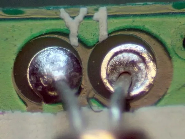
1. Visual Inspection
To look for cold solder joints, magnifying glasses, flashlights, and other aids to the eye are frequently required for a close examination. The first thing to look for when performing this visual inspection should be the joint color.
Next, we look at the form of the solder joint. If it is deformed or non-concave shape, it indicates that the solder alloy was probably not heated enough to melt completely. As a result, the joint may heat up and eventually split apart from the board due to resistance. Next, use the torch and magnifying glass to examine any joints for light leakage. If any light shows through the joint, it is not adequately bonded and requires rework.
Finally, tilt the board to see whether any joints are partially loosening from the board's base. In addition, the board needs to be inspected for overspills, which have the potential to generate short circuits that might destroy the entire thing.
2. Testing with a Multimeter
When identifying a cold solder joint with a multimeter, it's essential to focus on the electrical characteristics of the joint. You can start by setting the multimeter to the continuity or resistance mode. Next, unpower the circuit and place the multimeter probes on either side of the solder joint. A properly soldered joint should exhibit low resistance or continuity, indicating a solid electrical connection.
In contrast, a cold solder joint may display higher resistance or intermittent continuity. Therefore, you should pay attention to readings that fluctuate or deviate from the expected values. These irregularities suggest a weakened connection that requires attention. Moreover, using the multimeter to assess electrical continuity provides a precise method for identifying cold solder joints and ensuring the reliability of electronic connections.
3. Electrical Testing
Electrical testing, which offers information on the dependability and integrity of electrical connections, is crucial in locating cold solder joints. Using a multimeter might provide essential details on the solder joints during this procedure.
Another useful electrical test is to measure the resistance across the solder connection and continuity testing. Low resistance is a characteristic of a well-formed solder junction that guarantees effective electrical conductivity. A cold solder junction may cause higher-than-expected resistance, suggesting poor bonding and possible performance problems.
These electrical tests act as preventive measures throughout the soldering process and aid in identifying cold solder joints that may already be present. By integrating these inspections into quality control protocols, you may guarantee the establishment of sturdy electrical connections, reducing the possibility of irregular operation and augmenting the general dependability of electronic devices.
How Do You Repair an Existing Cold Solder Joint?
Fortunately, repairing cold solder junctions is not too difficult. So, let's find out how you can do it.
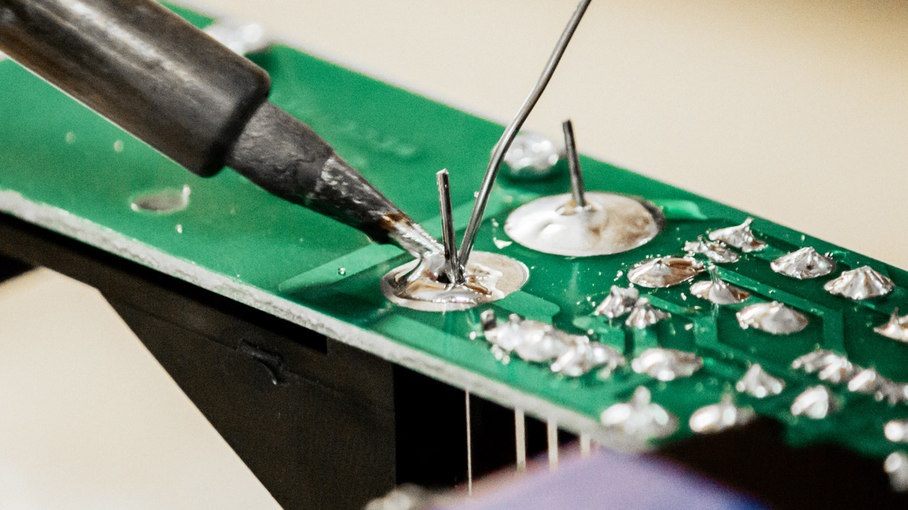
1. Firstly, Warm the Joint
Locate the joint and heat it so that the solder flows uniformly. For this, you can use hot air or a soldering iron. To properly heat the joint, apply heat evenly, taking care not to overheat the joint. If possible, use a soldering iron with a temperature control to ensure exact temperature control. Additionally, if necessary, you can also add extra solder.
Once you're done heating the joint, examine the cold solder again to ensure it is sturdy and error-free. To guarantee a proper fit, you might also need to file or sand the edges of the two parts that are being joined.
2. Take off the Extra Solder
Heat distribution may be challenging if the joint has excessive solder on it. As a result, the junction may weaken, and the solder flows unevenly.
Here's how to remove the extra solder:
● Use a desoldering tool or the pointed end of a soldering iron to scrape off the excess solder.
● Wait for the excess solder to melt by pressing the iron or tool's tip against it.
● Slowly wick away the hot solder using a section of desoldering braid.
● After removing the extra solder, inspect the junction and ensure no gaps and voids. If not, you must first fill them out to continue.
● Re-flush the junction and use the soldering iron to warm it up. The flux will stop oxidation and aid in the uniform flow of the new solder.
● Lastly, wait for the joint to cool before applying a new solder.
After the joint has cooled, ensure it is secure and free of gaps or voids. If the connection is still insecure, you can try doing it again.
During the process, you must remember to replace the part if the cold solder joint is on a crucial connection.
How to Prevent Cold Solder Joint
While it is true that frequent repairs of cold solder junctions are an unfortunate reality, several preventative measures can be implemented. So, let's look at them in detail.
1. Use an Appropriate Reflow Profile
One effective measure is to use an appropriate reflow profile during the soldering process. A reflow profile refers to the temperature-time curve applied in soldering. Ensure that the solder paste reaches and maintains the required temperature for an adequate duration, allowing for proper wetting and bonding.
This can be achieved by following the recommended reflow profile provided by the solder manufacturer or component datasheet. Pay attention to the preheat, soak, and reflow phases, as deviations in temperature or duration at any stage can lead to insufficient solder flow and, consequently, cold joints.
2. Proper Cleaning of Components
Properly clean your components with a general solvent to remove grease or any other impurity that can interfere with the soldering process. The soldering tools should be cleaned regularly and stored in a dry, dust-free enclosure to avoid contamination.
3. Remove Vibration Sources
Another reason for the cold solder joint is the vibration and movement that disturbs the joint during the cooling process. To prevent this, you should invest in a sturdy workspace to remove the vibratory sources. Consider employing anti-static tools like floor mats or wrist restraints if working with delicate components. You can also use a solder mask to stop further disruptions during the cooling process.
Frequently Asked Questions
1) What are Common Soldering Issues?
Common soldering issues include cold and dry joints. Cold joints occur when the solder doesn't correctly flow and adhere to the components, resulting in a weak connection. Dry joints occur when solder is insufficient, leading to poor electrical conductivity. Other issues may include solder bridges (unintended connections between adjacent pads), overheating (which can damage components), and insufficient or excessive solder.
2) What Does a Good Solder Joint Look Like?
A good solder joint exhibits a smooth, shiny surface with proper wetting, indicating that the solder has adequately flowed and adhered to both the component and the circuit board. The joint should have a consistent and even appearance without any gaps, cracks, or irregularities.
3) What's the Difference Between A Cold Joint and a Dry Joint?
While both are soldering issues, a cold joint refers to a solder connection where the solder didn't correctly melt and flow, leading to a weak bond. It often appears dull and may have a granular texture. On the other hand, a dry joint occurs when there's not enough solder, resulting in poor electrical conductivity. Dry joints typically have a matte or rough appearance. Both issues can impact the functionality and reliability of electronic circuits, making it essential to identify and address them during the soldering process.
Conclusion
A cold solder joint can be a nightmare for engineers but say no more because this article has covered it all! From understanding what they are to identifying, preventing, and repairing them, you know how to do it in simple and easy steps.
So, whether you're troubleshooting malfunctions or aiming for flawless soldering, we can be your go-to resource for achieving optimal electronic performance.