Global high-mix volume high-speed PCBA manufacturer
9:00 -18:00, Mon. - Fri. (GMT+8)
9:00 -12:00, Sat. (GMT+8)
(Except Chinese public holidays)
Global high-mix volume high-speed PCBA manufacturer
9:00 -18:00, Mon. - Fri. (GMT+8)
9:00 -12:00, Sat. (GMT+8)
(Except Chinese public holidays)
HomePage > Blog > Knowledge Base > What is a Circuit Card Assembly? | Circuit Card vs Circuit Board
Whenever talking about circuit board assembly, do you occasionally hear the word “circuit card assembly”? In the field of electronics, the terms "circuit card", "circuit board" and "circuit card assembly" are often mentioned. But what exactly do they refer to? Understanding these terms is crucial for electronics design and manufacturing professionals.
Read this article to help you fully understand circuit cards, circuit card assembly, and whether there are differences between circuit cards and circuit boards.
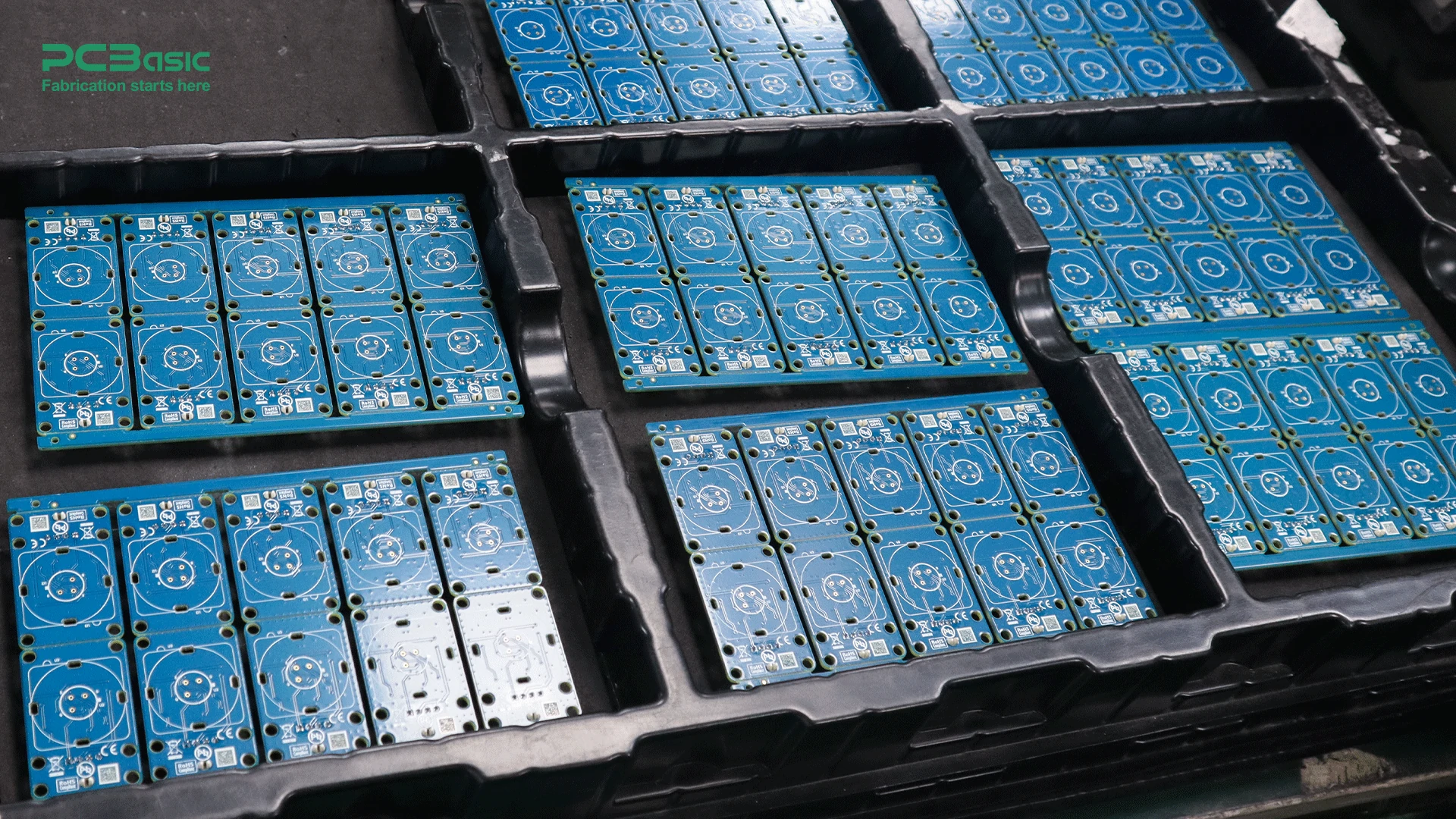
A Circuit Card, also known as a Printed Circuit Card, is a thin board used for mechanical support and electrical connection of electronic components. These components are usually mounted on circuit cards through a soldering process.
Time is money in your projects – and PCBasic gets it. PCBasic is the pcb assembly company that delivers fast, flawless results every time. Our comprehensive PCB Assembly Services include expert engineering support at every step, ensuring top quality in every board. As a leading PCB Assembly Manufacturer, we provide a one-stop solution that streamlines your supply chain. Partner with our advanced PCB Prototype Factory for quick turnarounds and superior results you can trust.
About PCBasic
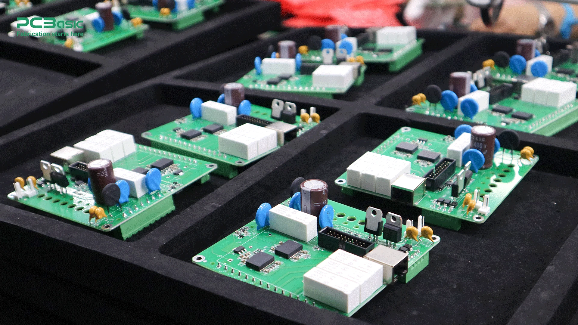
The circuit card assembly is fully assembled with a variety of components and functional circuits in place on the printed circuit card along, with connectors forms the final product. The key components of a CCA include a printed circuit board, electronic components and connectors.
A printed circuit board is the foundation of a circuit card assembly and typically consists of multiple layers of insulating materials like FR. 4 and copper traces. The insulating materials offer support and electrical isolation for the circuit whereas copper traces act as conductive paths to establish electrical connections among electronic components. Modern PCBs might feature layer layouts that permit intricate circuits to be incorporated within a confined area.
Electronic components are the most important part of the circuit card, and their assembly plays a key role in the design and performance of the circuit. Although there may be many different components on a circuit card assembly, there are several common components on almost every circuit card.
Connectors act as the bridges connecting circuit card assembly to systems or devices and play a crucial role in transmitting signals and providing power supply, or data interaction. They can range simple pin headers or complex multi-pin connectors, depending on the use and design needs to choose the right specifications.
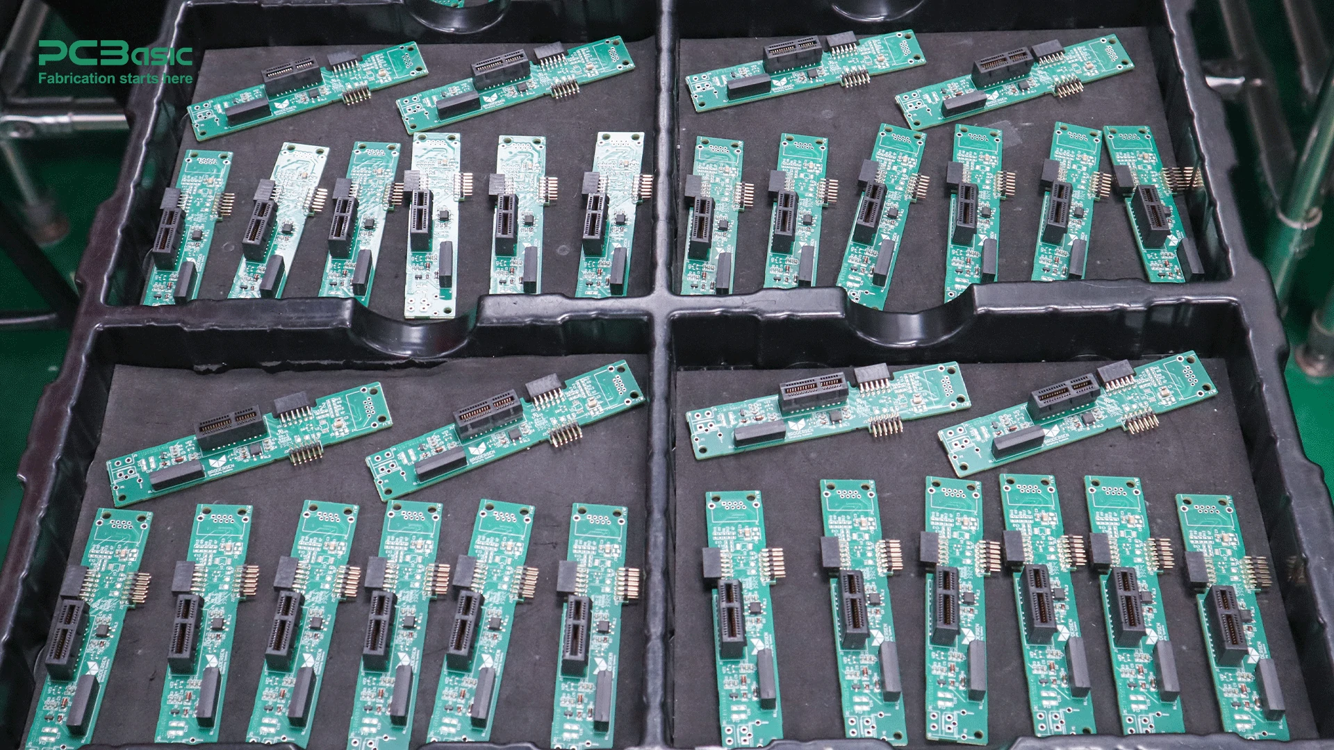
People often think that a circuit card is the same as a circuit board. Although “circuit card” and “circuit board” can be used interchangeably in many cases, in different contexts, the circuit card can represent different stages of the circuit board.
As we all know, a circuit board usually refers to the bare board that has not been assembled, without soldering any components. It is the basic part of the electronic system, mainly used in the design and development stage. A circuit board more emphasis on manufacturing process and wiring design, such as multi-layer board structure, trace width and pad layout design. Once assembled, the PCB becomes a PCBA.
In contrast, a circuit card can refer not only to the circuit board, but also to the circuit board that has been installed and assembled with electronic components. It contains a printed circuit board and all soldered components, such as resistors, capacitors, IC chips, etc. Circuit cards are often used for specific functional scenarios, such as Graphics cards or Network cards in computers. It is characterized by being assembled, equivalent to PCBA.
Circuit card assembly or circuit card assembly manufacturing process is an intricate, accurate process. Transforming an empty card to a ready-to-use electronic component, each step matters, including solder paste application, component placement, reflow soldering and inspection and testing, which is the same as circuit board assembly.
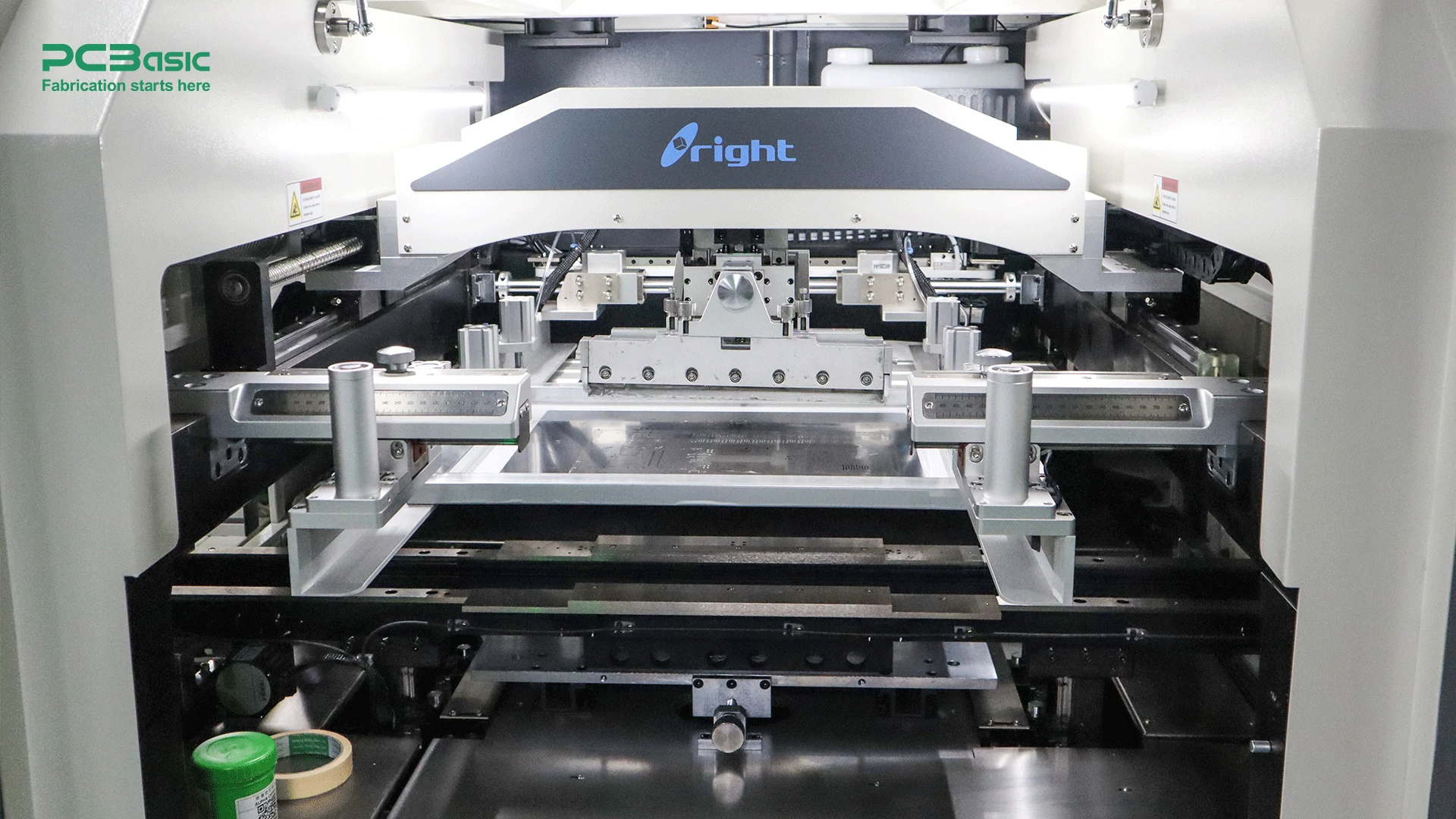
The first step in the process of circuit card assembly manufacturing is the solder paste application, where steel is used to apply an even layer of solder paste to the associated solder pad on the circuit card. This is the foundation for placing and soldering components. Solder paste combines solder particles and flux to both stabilize mechanically and guarantee good electric conductivity during soldering.
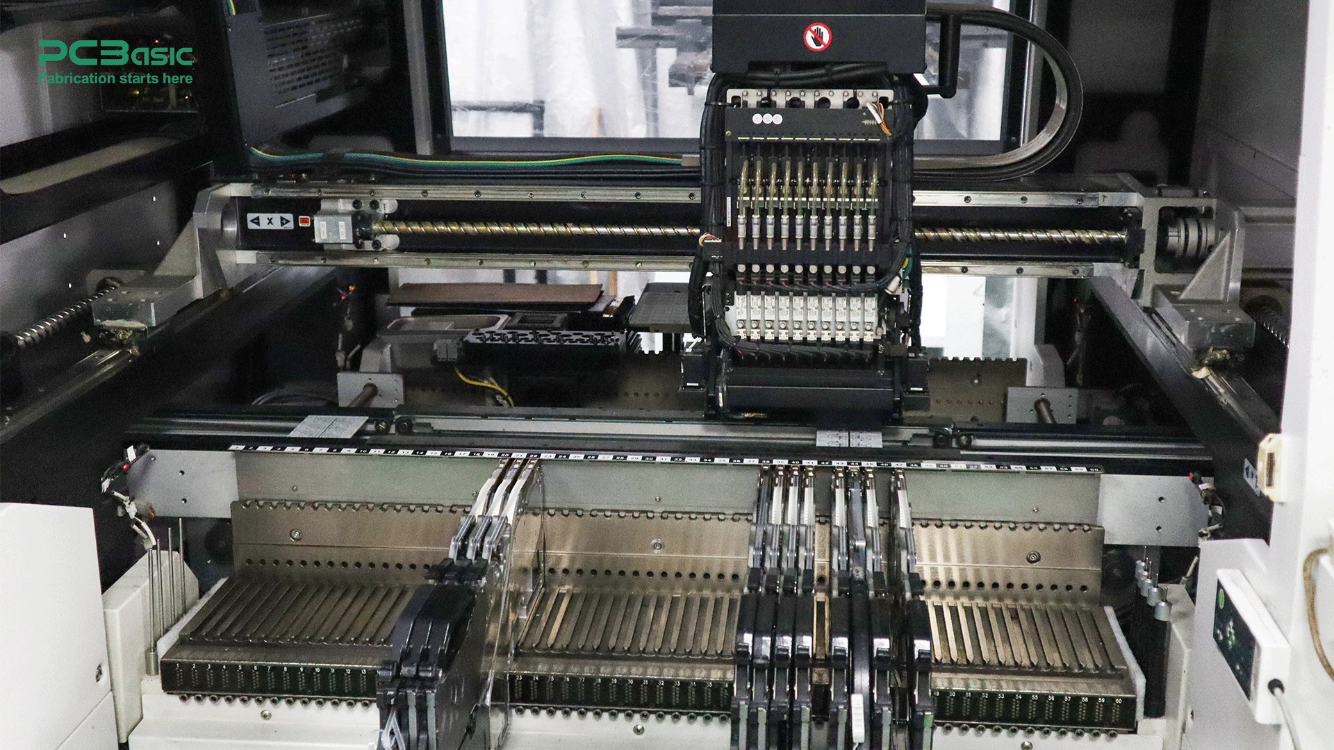
The next step is placing components. This is the process of placing electronic components, including resistors, capacitors, and IC chips, on a circuit card that has been pre-treated with an appropriate amount of solder paste. This is usually done using several automatic IC carry equipment, in which a pick-and-place machine picks up the equipment automatically and applies it into the places based on design, such as CAD, BOM etc. This approach provides accuracy and speed. Special or large components may require manual placement.
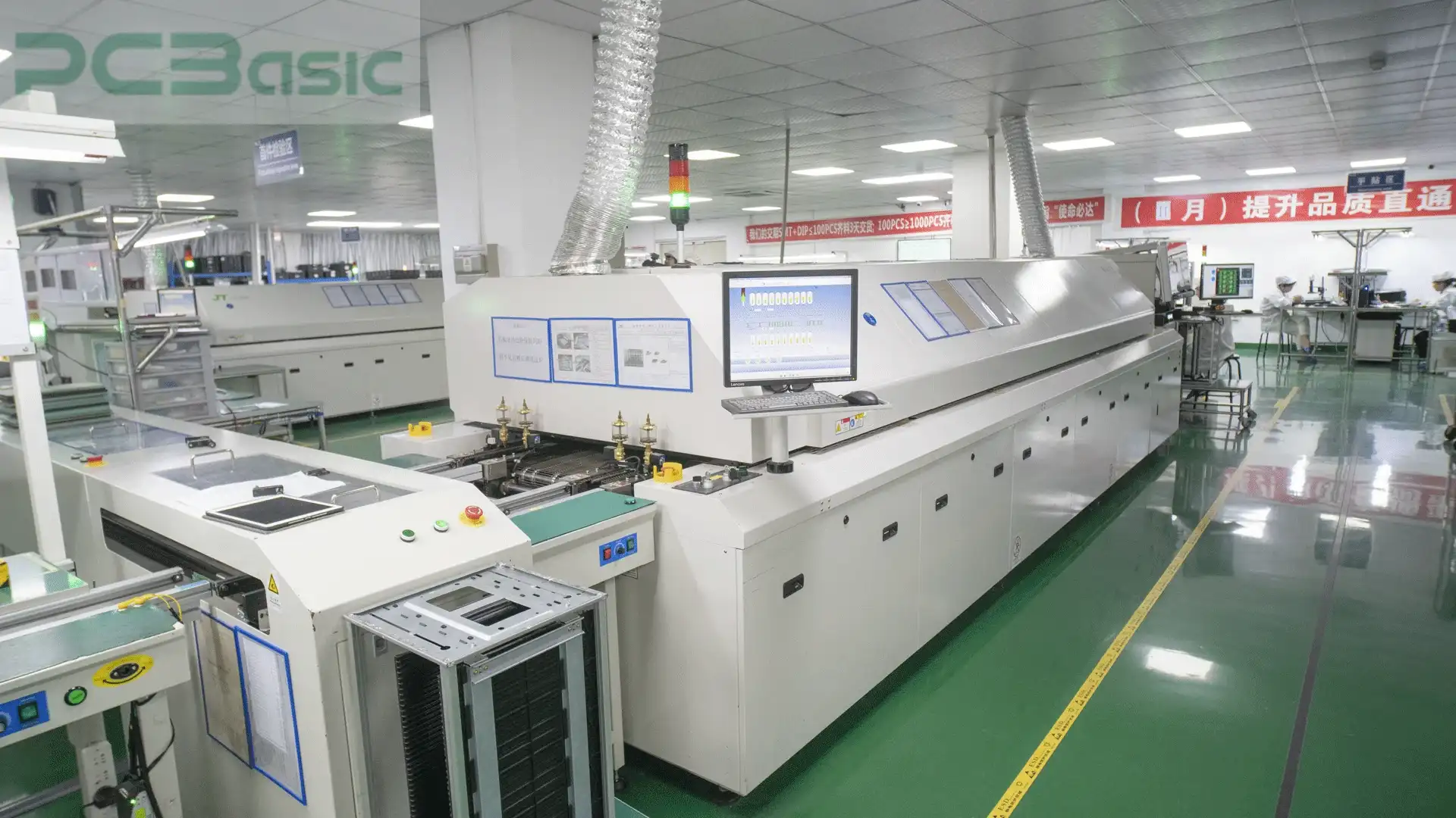
After the component placements, reflow soldering is coming. Reflow soldering involves placing a circuit card with mounted components onto a conveyor belt that moves through a reflow oven. In this process, the solder paste is melted by heating to form strong mechanical and electrical connections. The reflow oven is divided into multiple heating zones, with the temperature gradually increasing in each zone until it reaches the solder paste's melting point. After the circuit card passes through the cooling stage, the solder paste solidifies again, securing the components in place. This is the most critical soldering step in the manufacturing process, directly determining the reliability and performance of the components.
After all steps are finished, to ensure the reliability and performance of the assembly, multiple inspection and testing methods are conducted during the circuit card assembly manufacturing process to promptly identify and correct defects. Commonly used methods include Automated Optical Inspection (AOI), X-ray Inspection, Functional Testing, and Manual Inspection. These techniques are employed to ensure the quality and functionality of the circuit card assembly.
Based on different application scenarios, circuit card assemblies include single-sided assembly, double-sided assembly, multi-layer assembly, rigid, flexible, and rigid-flex assembly. Each type is tailored to specific functions and design requirements, reflecting the diversity and flexibility in circuit card assembly manufacturing.
Single-Sided Assembly refers to circuit card assembly where electronic components are mounted on only one side of the circuit card. They feature simple design and manufacturing processes with lower production costs, making them suitable for straightforward and cost-sensitive circuit designs.
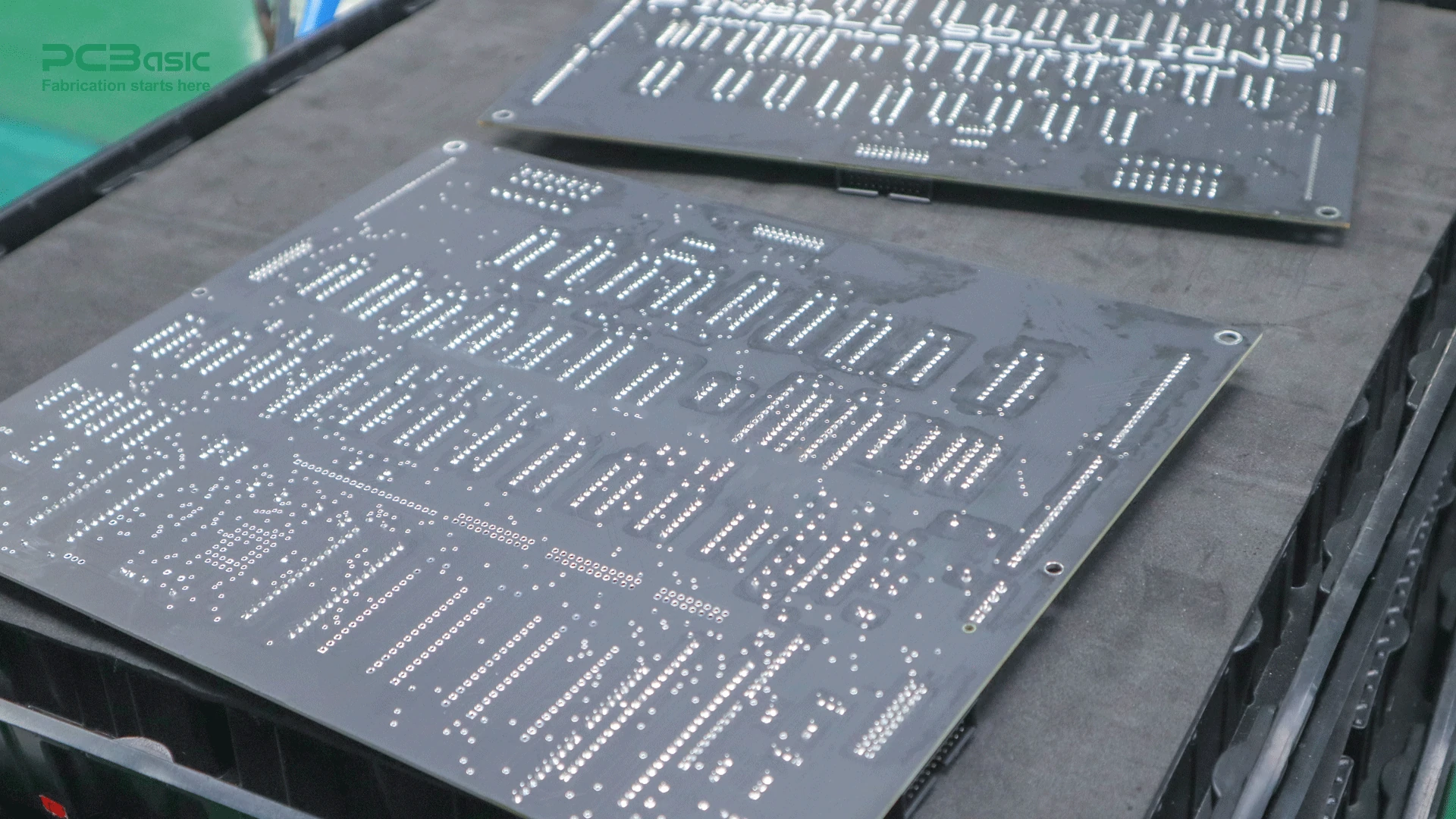
Double-Sided Assembly is circuit card assembly where components can be mounted on both sides of the circuit card. This significantly enhances component density and design flexibility, allowing for increased circuit complexity and higher component integration.
Multi-Layer Assembly consists of multiple conductive layers, typically involving circuit card designs with four or more layers. These conductive layers are interconnected through inner-layer connection technologies, supporting complex signal transmission and power distribution. Multi-layer assemblies offer improved signal integrity and electromagnetic interference (EMI) resistance, making them ideal for high-density and high-performance circuit requirements.
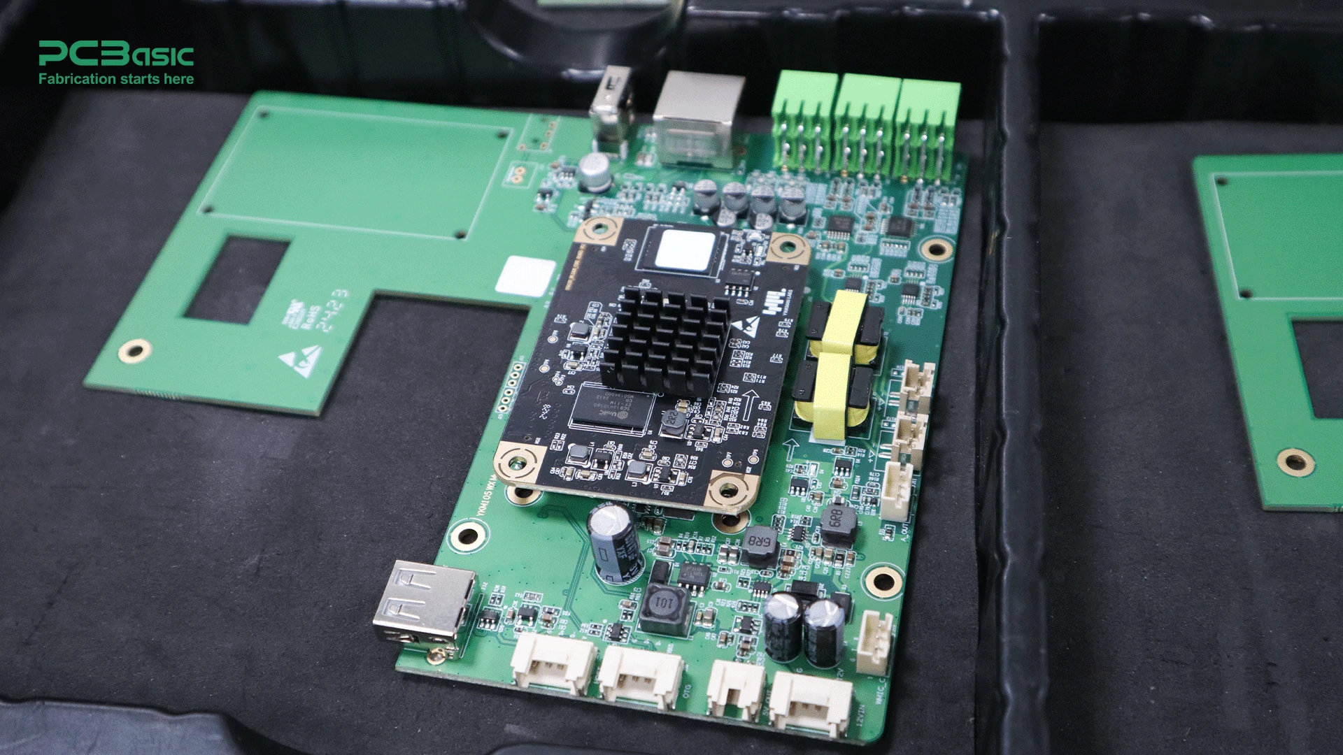
And finally, based on mechanical and spatial requirements, circuit cards can be designed as rigid, flexible, or rigid-flex structures. Rigid assemblies use rigid materials, such as FR4, providing mechanical strength and stability. Flexible assemblies use flexible substrates, such as polyimide, allowing the cards to bend or fold in confined spaces, making them suitable for lightweight and compact devices. Rigid-flex assemblies combine the mechanical strength of rigid sections with the flexibility of flexible sections, simplifying internal system wiring and reducing the need for connectors.
After reading this article, we know that even though circuit cards and circuit boards can be used interchangeably sometimes, in different situations, circuit cards can also be different stages of the circuit board. Therefore, it is important to understand the meaning of circuit card assembly, its assembly process and the difference between circuit card and circuit board.

Assembly Enquiry
Instant Quote
Phone contact

+86-755-27218592
In addition, we've prepared a Help Center. We recommend checking it before reaching out, as your question and its answer may already be clearly explained there.
Wechat Support

In addition, we've prepared a Help Center. We recommend checking it before reaching out, as your question and its answer may already be clearly explained there.
WhatsApp Support

In addition, we've prepared a Help Center. We recommend checking it before reaching out, as your question and its answer may already be clearly explained there.
