Global high-mix volume high-speed Shenzhen PCBA manufacturer

Ru
9:00 -18:00, Mon. - Fri. (GMT+8)
9:00 -12:00, Sat. (GMT+8)
(Except Chinese public holidays)


Global high-mix volume high-speed Shenzhen PCBA manufacturer

Ru
9:00 -18:00, Mon. - Fri. (GMT+8)
9:00 -12:00, Sat. (GMT+8)
(Except Chinese public holidays)


Early electronic project creation used the point-to-point manufacturing process. But in the 1950s, the 2nd generation of computer electronic projects made on PCBs were created using through-hole technology (THT). With the advances in this technology, SMT is introduced, replacing the older through-hole technology (THT), but in larger power projects, through hole assembly technology is still used. Currently, primarily SMT-based boards are created, but for interconnections of different layers of PCBs, stills are made by using through-hole assembly technology, such as other types of board vias like through-hole vias. Next, this post will look at through-hole PCB assembly and its differences from SMT assembly.
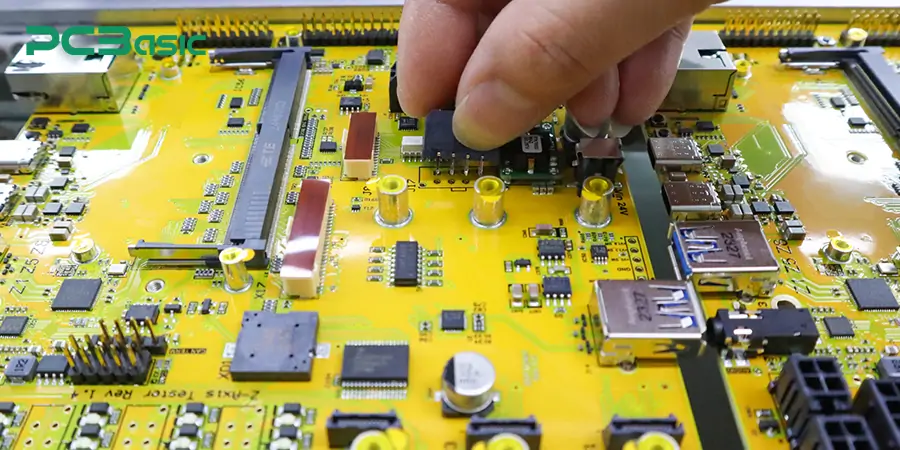
Through-hole PCB assembly is a technique in which components are connected on board, passing their leads through drilled holes on the surface of the PCB. When components' leads are passed through, holes are soldered on both sides to make conductive paths. Manual or wave soldering is commonly used to make strong connections between board and components.
Different types of PCBs are used in electronic projects: single-sided, double-sided, or multiple-layer. In older electronic projects, they were made with single or double layers, and these boards were made using through-hole PCB assmebly technology, but multilayer boards were commonly used with advanced technology. In these boards, through-hole assembly technology did not fulfill the electronic needs as it took more places for component placement, so it was replaced with SMT assembly technology.
However, through-hole PCB assembly is still used in different projects and as a combination of SMT assembly. Its use in larger-size projects is preferred since any component damaged or has to be repaired can easily be separated from the board compared to SMT components. Their stable structure makes them suitable for use in projects where high thermal stress is involved. In the 1980s, when SMT assembly became everyday use, it was thought that THT (Through Hole Technology) assembly would soon end, but still, it is used and has importance in the electronic industry.

Through hole PCB assembly has its advantages and disadvantages:
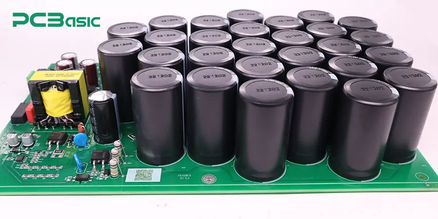
● Through hole assembly process handles more significant-sized components (through hole components) , and it is used in high-power components in electronics and industries where larger power-consuming machines are used.
● There will be strong connections of through hole components on the board with the use of the THT technique since it involves the soldering of components on both sides of the board selpt. Strong component connections help create a high-strength THT pcb board that can easily withstand stress and environmental conditions such as temperature and pressure changes.
● Larger THT PCB boards are made with through hole assembly process to dissipate heat from components quickly. So, it is used in power electronics since it needs a high power management process.
● In this through hole PCB assembly, component repair is an easy process.
● THT assembled PCB board does not provide the required density for projects since it makes less dense boards. In high-density design, instead of THT, SMT is used since it can be small components in high-density layout.
● Through hole PCB assembly is not used for less-weight projects; a small size is needed since through hole components are more significant than SMT components.
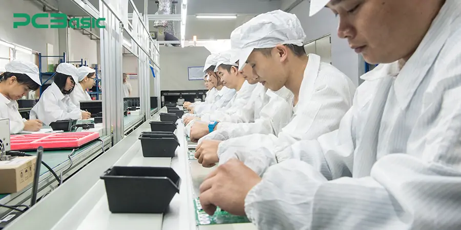
● Through hole PCB assembly is a slow process since it uses a manual component connection process. That makes it a more costly and time-consuming method than SMT assembly.
|
Aspect |
Through-Hole Assembly |
Surface-Mount Assembly |
|
Mounting |
Pins inserted through holes |
Mounted directly on the PCB surface |
|
Component Size |
Larger |
Smaller |
|
Board Space |
Occupies more space |
Space-efficient |
|
Mechanical Strength |
Stronger mechanical bond |
Less durable mechanically |
|
Cost |
Higher due to manual labor |
Lower with automated assembly |
|
Typical Use |
Power electronics, connectors |
Consumer devices, compact electronics |
●Through hole PCB assembly is used in industries to make high-weight machines that operate at different temperatures. It is used to ensure the reliable operation of sensors and control systems.
●THT PCB assembly is used in medical devices, such as diagnostic and implantable devices.
●Automobile electronics that come with an engine control system use THT assembly. This process helps to make components strongly connected to handle high temperatures and vibrations.
●Devices used in aviation also use THT to connect components since the aviation industry needs high mechanical strength components.
●Through-hole PCB assembly is also used to make military tools that can operate under challenging conditions and handle harsh weather.

There are three common steps of the THT assembly process.
Component Insertion
In this process, pins of through-hole components, like resistors, diodes, etc., pass through the holes made on boards.
Soldering:
They are soldered after passing the component pins or leads in the holes on the board. That is, the metallic alloy has a lower melting point and connects the leads of components on board. This process ensures a solid electrical path. The types of soldering commonly used in through-hole assembly are wave and selective soldering. Wave soldering is used for high-volume through-hole assembly. While selective soldering uses a solder molder to apply molted solder to make connections
Cleaning:
In this step, residual flex on the board is removed. Flux residues are removed during soldering to avoid corrosion and electrical interference. For the cleaning process, brushes and solvents are used.

PCBasic is focused on providing high quality through hole PCB assembly services to customers around the world. With more than 15 years of industry experience, PCBasic has become one of the leading through hole PCB assembly factories in China, trusted by engineers, start-ups and OEM customers.
PCBasic provides a full-process, through-hole PCB assembly service, including:
As an experienced through hole PCB assembly supplier, we have advanced through hole PCB assembly equipment and a strict quality control system to cope with a variety of complex projects. We have experienced technical team and automation through hole assembly production line, perfect testing and quality assurance system, can serve a wide range of automotive, industrial, medical and other industries customers. Whether you need a small batch of through hole PCB assembly trial production, or looking for long-term cooperation with China through hole PCB assembly supplier, PCBasic can be your stable and reliable partner.
As it is an old assembly process, it has adapted to miniaturization. The use of advancements and new manufacturing techniques helps to make small and less THT components have compact designs.
Due to environmental safety, industries are using lead-free solder alloys. This adaptability of lead-free alloys is due to eco-friendly manufacturing techniques used in through-hole assembly.
With the use of selective soldering machines, THT has become able to solder certain components at specific points. This process minimizes the chances of thermal stress on sensitive parts and increases the quality of the solder joint.
Flux is considered the main component of soldering that has made some advancements. Using the latest flux process, we can get reliable THT since it has wetting features and fewer chances of errors due to good solder flow.
The features of THT assembly that allow us to adapt different component types and their sizes make it best to provide features like customization, prototyping, and high flexibility.
● This technique does not get high component density on board since it involves holes that also need some space to create. The solution to this limitation is using THT with SMT, a hybrid assembly process.
● Another limitation is that it requires manual labor for component insertion in the holes, making it costly and slow. To solve this issue, use robotic component insertion techniques that have fewer chances of error and reduce time and cost.
● Wave soldering is used in this process since it has a high heat that affects the sensitive component. So best option is to use selective soldering instead of wave soldering to target the specific part on board and affect the neighboring parts.
1. The quality of sensitive board components can be maintained with selective soldering that reduces thermal stress on another component, the targeted part of the boards.
2. Manual labor for THT is costly, so using an automated component connection process minimizes the cost and makes effective connections. Automatic machines connect more components in less time than manual component connections.
3. Using an accurate cleaning method for flux residues avoids the effects of corrosion and any defects on board and, as a result, increases the efficiency of THA.
THT is the best PCB mounting technique for making larger-sized boards or multiple layers. It is a cost-effective solution for prototypes and board testing and is also preferred for high mechanical strength component mounting.
However, it is preferred for something other than high-density design where SMT makes high-speed assembly less weight board. All in all, using either SMT or THT is based on the type of project and its requirements. For high-density projects, SMT is preferred, and for larger-size and high-power projects, THT is used.
For more information about your PCB-based project and which type of assembly it needs, contact PCBasic, your best PCBA manufacturer.
Assembly Enquiry
Instant Quote