
Global high-mix volume high-speed PCBA manufacturer
9:00 -18:00, Mon. - Fri. (GMT+8)
9:00 -12:00, Sat. (GMT+8)
(Except Chinese public holidays)





HomePage > Blog > Knowledge Base > What Does a GPS Tracker PCB Project Need Before Assembly?
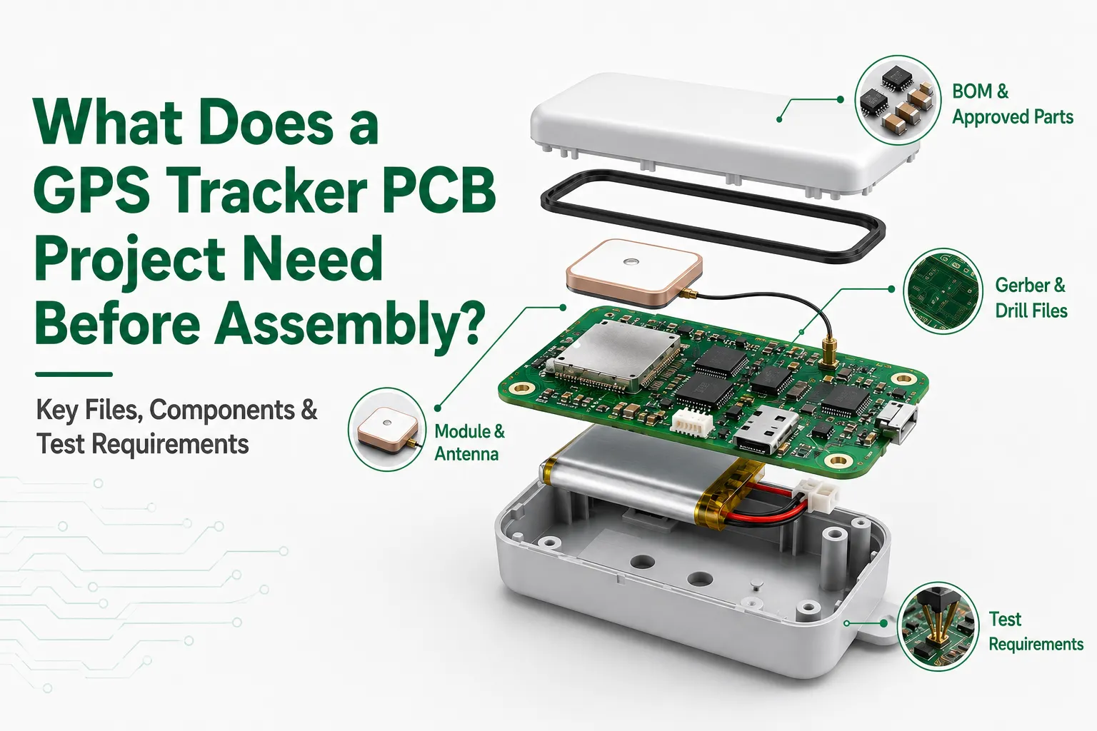
Table of Contents
1. Why Is a GPS Tracker PCB More Than a Standalone Board?
2. Which Risks Should Be Mapped Before GPS Tracking PCB Assembly?
3. How Should Assembly Controls Match Components That Can Fail Quietly?
4. What Should a GPS Tracking PCBA Functional Test Recreate?
A GPS tracker PCB may function properly on engineering bench. It can be powered on, locate accurately, and send data normally. However, when it is actually installed in a vehicle, outdoor equipment, or battery-powered product, the situation may be quite different. The equipment is in motion, so the communication module needs to constantly send and receive data. The current demand is not constant either, and the connector may also be affected by vibrations or cable pulling. Problems that were not exposed during testing may arise at this time, such as unstable positioning, communication interruptions, or even sudden resets.
This is why the assembly of GPS tracker PCBs cannot be judged merely by whether the components are properly soldered or if the board can be powered on normally. Before formal production, manufacturers also need to know how this board will actually function: which components and interfaces are the most critical, what kind of load changes the power supply will undergo, what state the positioning and communication should reach, and what kind of test results can truly be considered as passing. The earlier these requirements are clarified, the easier it will be to control the subsequent assembly and testing; if the product does have subsequent abnormalities, it will also be easier to determine where the problem lies.
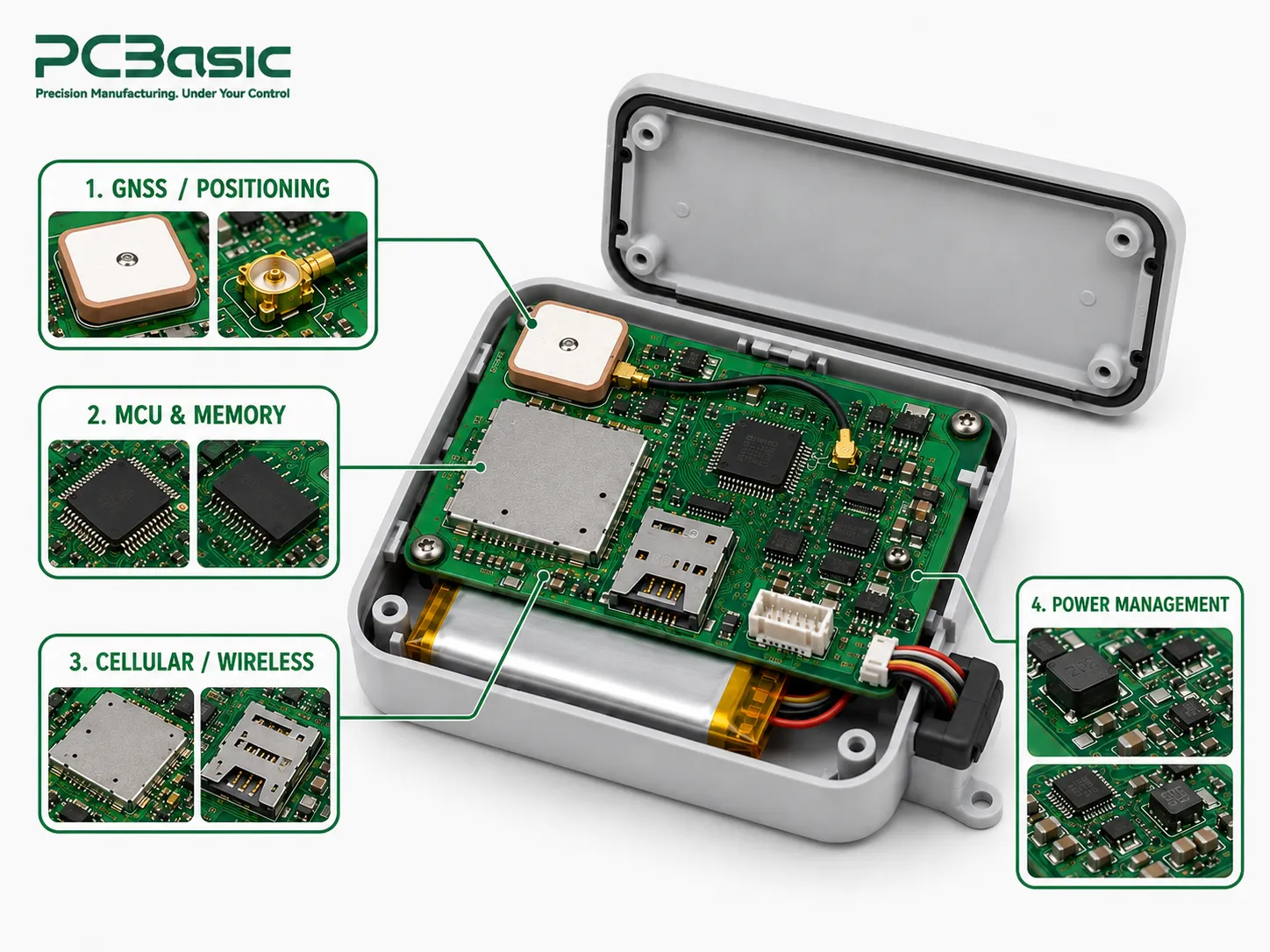
A GPS tracker PCB is not merely responsible for positioning; several key components need to work together:
• Positioning: The GNSS module receives positioning signal through the antenna.
• Control and storage: The processor is responsible for processing data, while the memory stores configuration, timestamps or buffered records.
• Communication: Data is sent via cellular, Wi-Fi or Bluetooth.
• Power: The battery and power management circuit ensure the stable operation of these functions.
However, in the actual production process, the issues that each module needs to pay attention to are not the same. For instance, the connector may seem to be properly installed, but when the cable is pulled, the contact might become unstable; some modules with shielding covers may not show any abnormalities from the outside, but the real problem lies in the solder joints beneath. There is another situation that is even harder to detect: when the board is stationary, everything is fine, but once communication or positioning starts, the power consumption increases, and it suddenly resets. If there are flexible or hybrid flexible-rigid areas in the design, the bending method also needs to be considered in advance. Many problems are actually not noticeable when inspected horizontally.
Before requesting a GPS tracker PCB assembly quote, it helps a lot to first clearly understand the entire workflow: where the signal enters, how the data is processed and stored, and finally how it is sent out. You can also mark out which modules, connectors, power sections or hidden solder joints need carefully check at this step. Another important point is: which are just design expectations and which functions must be truly tested on the finished board need to be clearly distinguished in advance. This makes later inspection and functional testing more meaningful. Instead of simply checking whether the board “looks good”, you are confirming whether it can actually perform the tracking functions.
A truly valuable review should be conducted before the first board enters production. You can start by checking the most basic manufacturing data. Gerber file usually describes graphic information such as copper layers, solder mask, and screen printing, while NC/Excellon files mainly record drilling data. However, Gerber is only a part of it. The stack-up, manufacturing drawings, component placement coordinates, BOM, assembly drawings, module data, and test standards each address different issues and cannot simply be substituted for each other.
In the BOM, it is necessary to clearly list the acceptable alternative materials. The assembly drawing needs to indicate polarity, connector orientation, shielding and special processes. If there are any bending requirements in the flexible area, the position, radius and folding state should also be defined in advance. The connection method between the module and the antenna, as well as the testing conditions, should also be clearly described, rather than leaving production staff to judge from a picture.
The following table can help you break down the general tracking requirements into specific contents that need to be confirmed before production. It cannot replace circuit, RF, firmware, casing or on-site testing, but it can help clarify the key risks and inspection priorities. This way, the assembly team and the product team can make inspections and tests based on the same set of requirements later, rather than each having their own understanding of a different set of standards.
|
Board area |
Main risk |
Key check |
Buyer input |
|
GNSS module & antenna |
Weak or unstable positioning |
Module orientation, antenna connection, grounding |
Module data, antenna type, test condition |
|
Communication section |
Data drops or resets during transmission |
Module placement, power behavior, and communication path |
Interface definition, supply range, pass criteria |
|
Controller & memory |
Data loss or abnormal tracking behavior |
Programming, memory setup, functional test |
Firmware version, expected output |
|
Power section |
Resets when current demand changes |
Input range, regulator output, load conditions |
Battery profile, load, acceptance limits |
|
Connectors & flex areas |
Intermittent contact or mechanical damage |
Orientation, bend location, cable or fixture access |
Connector drawing, cable route, flex requirement |
After separating these risks, the next step is to determine in which stage each issue should be identified. Some can be checked during the assembly process, while others need to be verified through subsequent tests.
The GPS tracker PCB assembly plan should be arranged according to the packaging on the board and the actual risks. Before the production starts, incoming material inspection will first confirm whether the components, modules, connectors, and humidity-sensitive materials are consistent with the approved BOM. After entering SMT, solder paste printing, SPI, placement, reflow soldering, and AOI will respectively check different issues. If there are BGA or other hidden soldering points packaging on the board, X-ray may be needed for a closer look, and the inspection location and criteria should be clearly defined in advance. Through-hole components or large connectors may require THT assembly with wave or selective soldering, followed by checks on their installation and mechanical condition.
Don't just write "Check the circuit board". The specific locations to focus on, the criteria for judgment, and the procedures to follow when problems are identified should all be clearly stated beforehand. Requirements such as connector orientation, flexible board folding method, or battery interface restrictions should also be directly included in the formal assembly and testing documents rather than scattered in emails.
For the tracker project, what is truly useful is not how many devices the supplier has listed, but whether these devices and processes can solve the specific problems on your board. For example, which positions need to be checked with priority, which issues need to be confirmed through functional testing, and which results need to be recorded. PCBasic's PCB assembly services cover the main stages from materials, assembly to inspection and testing. Before determining the quotation range, you can first confirm which processes are truly needed based on the project's risks and testing requirements.
The same applies to component substitution. A part should not be treated as a direct replacement just because the size and package look the same. What really matters is whether it will affect electrical performance, heat dissipation, firmware or the final functionality. Manufacturers can assist in comparing materials and parameters, but if the substitute material may change the positioning, communication or other actual performance, ultimately it still needs to be confirmed by the product team whether to accept it.
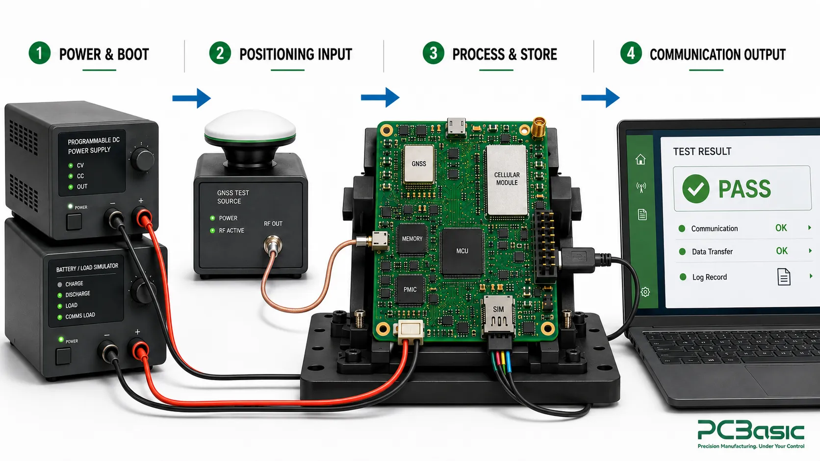
The assembly inspection mainly focuses on whether the components are correctly installed and whether the solder joints meet the requirements. The functional test, on the other hand, concerns another matter: after this board is powered on, can it complete all the tasks it is supposed to do? For GPS tracking PCBA, the testing is not only to confirm that "it can start up", but also to see if it can normally obtain positioning information, process and save data, and send the results through the set communication method.
Simply writing “power on and check GPS” is not enough if you want the test results to be comparable. A different firmware version, antenna connection, or even power condition can change the result. Therefore, the most important aspect of functional testing is not to merely record "Pass" or "Fail", but to clearly state under what conditions the test was conducted. The PCB and firmware versions, power supply method, communication path, test time, and expected results should all be traceable; if any special fixtures or signal sources were used, their corresponding configurations should also be retained.
A GPS tracking PCBA functional test also needs a clear line between design validation and production verification. The manufacturer can be responsible for assembly, preparing fixtures, conducting the agreed tests and keeping records, but "what constitutes a qualified positioning performance" cannot be judged by the factory itself. Requirements such as positioning accuracy, reporting frequency, data format, power supply status or communication performance still need to be defined by the product team in advance. After all, these standards cannot be derived from just a BOM.
The first article test result should not merely consist of a "Pass" or "Fail". Record the PCB and BOM version used at that time, the configuration of key modules, fixtures and test conditions. In this way, if there are problems in subsequent batches, it will be easier to review and determine whether it is due to changes in materials, assembly issues, firmware, connectors, or changes in test conditions.
PCBasic’s MES-supported flow can retain records of incoming materials, first pieces, production processes and functional tests, facilitating subsequent traceability. However, for these records to be truly useful, the test conditions must be clearly defined so that they can be re-verified using the same method in the future. For instance, the BGA X-Ray inspection video of PCBasic demonstrates how hidden solder joints are inspected. However, X-Ray can only detect problems at the welding level. The normality of GPS positioning, data processing and communication still needs to be confirmed through functional tests.
Before requesting a quote, it is advisable to prepare Gerber files, drilling files, BOM, soldering coordinates and assembly drawings in advance. At the same time, supplementary materials such as modules, antennas, power supplies, connectors, firmware and functional test-related information should also be provided. If there are flexible or hybrid flexible-rigid areas on the board, the bending positions and bending radii need to be defined in advance. The more complete the materials are, the easier it is for the supplier to determine what level of production, testing and testing is required.
It is also fine if some details are not final yet, but they should be clearly identified. For instance, if the antenna, enclosure, battery plan or firmware are still being adjusted, they can be treated as a hypothetical quote at this stage, rather than making the supplier mistakenly believe that these conditions have been fixed. This way, when entering the first batch or small-scale trial production later, it will be easier to determine whether the problem lies in the product itself or in the production process.
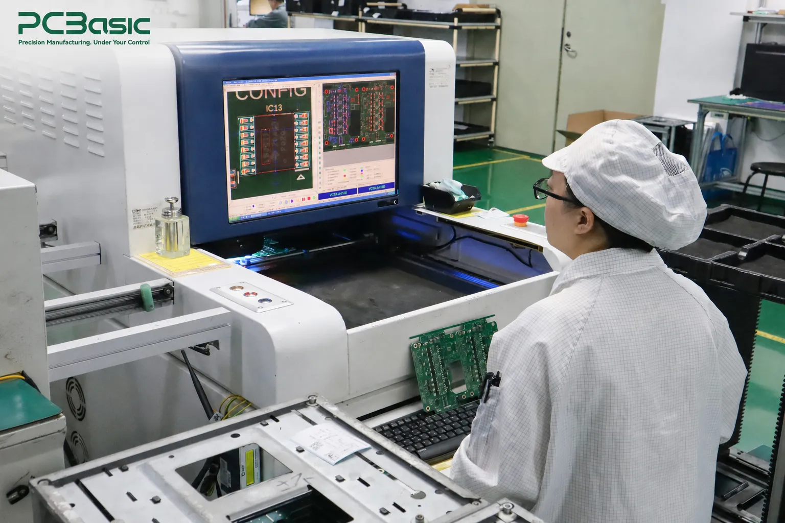
In addition, the quotation should not have only one unit price. What is even more valuable is whether the supplier can proactively indicate any material shortages, packaging risks, jig requirements, and which test conditions still need to be confirmed by the customer. The manufacturing overview of PCBasic shows the overall process from procurement, assembly to inspection and testing. However, the final quotation and production plan should still be based on the actual data and acceptance requirements of this GPS tracker PCB.

The reliability of GPS tracking for PCBs is never determined by any single process alone. What truly matters is that it can still operate stably under actual working conditions such as positioning, communication, and load variations. The risk identification, assembly control, and functional testing mentioned earlier are ultimately aimed at identifying these issues as early as possible, rather than dealing with them after the product is put into the field. To achieve this, the production materials, testing conditions, and key records also need to be clearly defined as much as possible before the project begins, so that when there are changes or abnormalities later on, there will be a basis for tracing.
If your design is ready for manufacturing review, it is best to prepare all the necessary information such as Gerber files, BOM, assembly data, module and antenna details, as well as functional test requirements. By submitting these materials through the engineering review form of PCBasic, you can first confirm what needs to be supplemented in terms of assembly, inspection, testing and fixtures, and then proceed to the formal quotation and production.
Q1: What should a GPS tracker PCB package include before assembly?
A1: Include the PCB revision, Gerber and NC drill files, stack-up, fabrication and assembly drawings, pick-and-place data, BOM and approved alternates, module and antenna information, connector and cable details, power and battery conditions, enclosure constraints, firmware reference, and written functional pass/fail criteria. Add bend locations and bend-radius limits if the assembly includes flex sections.
Q2: When does a GPS tracking PCB need X-ray inspection?
A2: X-ray is useful when the board contains BGA or other hidden solder joints that cannot be assessed visually. Name the affected reference designators and inspection criteria in the build package. X-ray supports assembly verification, but it does not prove that the tracker can acquire, process, store, or report location data; those functions require a separate test.
Q3: How can a GPS PCBA move from a prototype to repeat production?
A3: Freeze the PCB revision, approved BOM and alternates, module and antenna configuration, assembly instructions, first-article criteria, fixture version, and functional-test record. Use the same acceptance conditions for later builds, and investigate changes in material, process, firmware, connector configuration, flex state, or test setup before treating results as comparable.

Assembly Enquiry
Instant Quote





Phone contact

+86-755-27218592
In addition, we've prepared a Help Center. We recommend checking it before reaching out, as your question and its answer may already be clearly explained there.
Wechat Support

In addition, we've prepared a Help Center. We recommend checking it before reaching out, as your question and its answer may already be clearly explained there.
WhatsApp Support

In addition, we've prepared a Help Center. We recommend checking it before reaching out, as your question and its answer may already be clearly explained there.
