Global high-mix volume high-speed PCBA manufacturer
9:00 -18:00, Mon. - Fri. (GMT+8)
9:00 -12:00, Sat. (GMT+8)
(Except Chinese public holidays)
Global high-mix volume high-speed PCBA manufacturer
9:00 -18:00, Mon. - Fri. (GMT+8)
9:00 -12:00, Sat. (GMT+8)
(Except Chinese public holidays)
HomePage > Blog > Knowledge Base > Rigid-flex PCBs vs. Flex PCBs
Advancements in wearable electronics demand small and curved enclosures, and PCBs and aerospace applications require high reliability and robust interconnections. Handheld electronic devices such as smartphones and digital cameras demand a lightweight with a reduced form factor. These demanding challenges are filled by Rigid flex-printed circuit boards that can bend and flex. Traditional PCBs are only rigid PCBs and are not flexible. Rigid-flex PCBs allow designers to design more complex, robust, and dense PCBs that are lightweight, have reduced weight and space, and increase performance. This makes rigid-flex PCBs a perfect choice for technological industries.

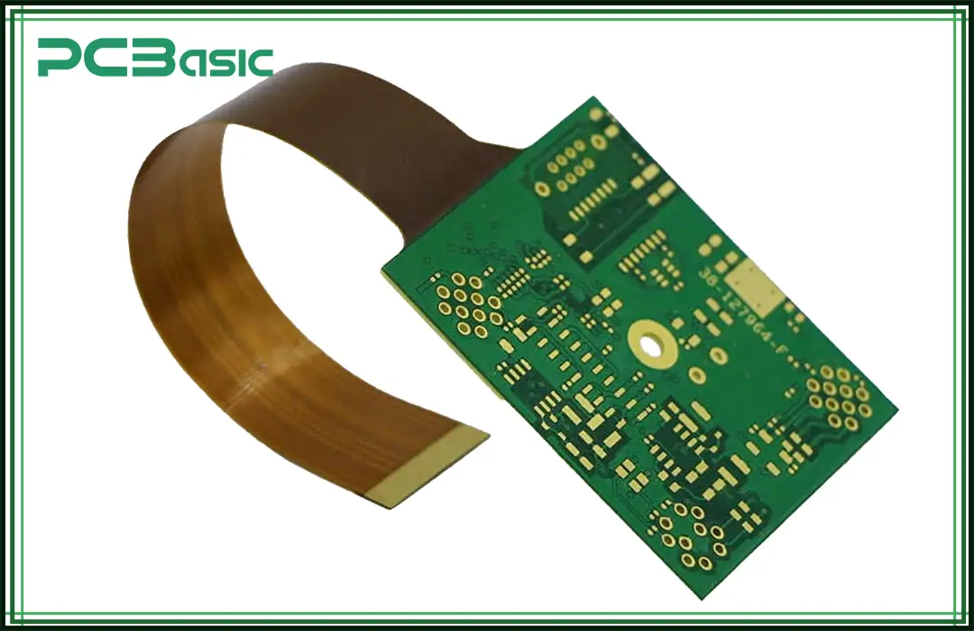
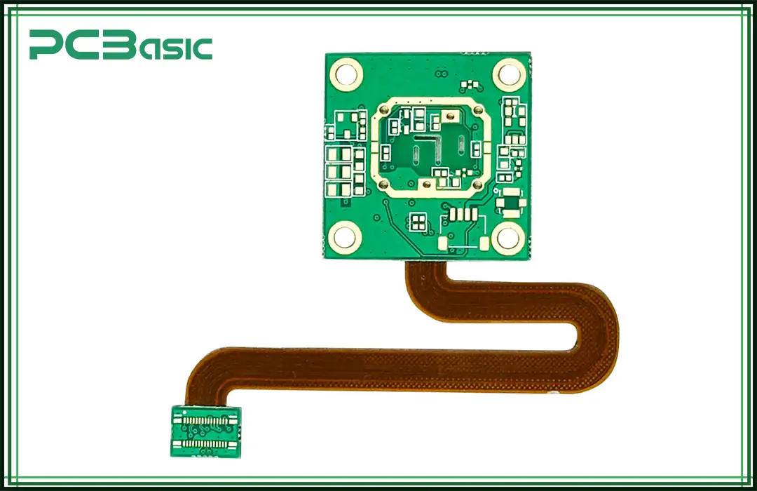
Rigid-flex printed circuit boards are a type of PCB technology that uses the benefits of both flexible and rigid substrate PCB technologies. This means that these boards have one rigid part and the other part is flexible and can easily be bent or flexed. Rigid-flex PCBs allow designers the creative freedom to design three-dimensional shapes across a diverse range of applications.
Both rigid and flexible sections have their specific purpose in the design. The rigid section is responsible for providing structural support and holding all the components. The flexible section is responsible for providing the interconnection between two rigid areas and allowing the bending and folding of PCBs. Depending on the type of application, either one or more flexible circuits are attached to rigid boards.
Rigid-flex printed circuit boards are widely used in a range of applications including medical devices, defense, wearable, and consumer electronics due to their flexibility, miniature size, and limited space conditions.
The term flex refers to the type of PCB that can bend and flex without breaking and rigid means PCB that is reliable and robust. The manufacturing process of a rigid-flex PCB is much more complex than a rigid PCB but it offers various capabilities over traditional rigid PCBs.
With rigid-flex PCB your device has several capabilities over traditional PCBs.
1. Enhanced Signal Integrity: Rigid-flex PCB minimizes the interconnects which reduces the noise and Electromagnetic Interference (EMI), resulting in improving signal integrity issues.
2. High Reliability: The rigid-flex printed circuit board reduces the risk of failure due to the minimum number of solder joints. The flexible section's capability allows the PCB to bend and flex without breaking. The flexibility of these boards allows them to bear harsh environmental conditions and high mechanical stress.
3. Compact and Space-efficient Design: With a rigid-flex PCB design, your product will have a smaller number of connectors and cables. This will make the device lightweight, smart, and compact which is suitable for many applications like medical devices, wearable electronics, and aerospace.
4. Improved Mechanical Stability: The flexibility of rigid-flex boards increases the device's ability to withstand higher mechanical stress and make them more stable.
Understanding rigid-flex PCB is important for designing a high-quality rigid-flex PCB for your device. The manufacturing process of rigid-flex PCB includes several important steps.
Step 1: Schematic Design
This is the first step in the manufacturing process, in which the design engineers define the rigid-flex PCB stack and design the detailed schematics of the device. Engineers also considered factors like material and bending radius of rigid-flex PCB in this phase and generated the final Gerber files. Designers mostly use Altium Designer and Autodesk Eagle to design rigid-flex PCBs.
Step 2: Select Material
Material selection is a critical step in creating a rigid-flex PCB. In this step, engineers choose materials for rigid and flexible PCB sections. Typically, FR4 material is used for rigid sections of the board, and polyimide is used for flexible PCB parts.
Step 3: PCB Drilling and Plating
Once the design is finalized, vias and holes are drilled into the PCB using laser or mechanical drilling. After the drilling, a thin layer of copper is deposited using a process known as plating to ensure electrical connectivity in holes. The plating process ensures that signal and power are effectively transferred between different layers of rigid-flex. The rigid-flex circuit board is also cut into its final shape using a laser or CNC machine.
Step 4: Lamination Process
In this step, both rigid and flexible layers of PCB are laminated under extreme temperature and mechanical stress to ensure that rigid-flex PCB has maximum structural bonding and mechanical stability.
Step 5: Component Placement
Rigid-flex PCB is now ready for the component placement. Firstly, solder paste is applied to component pads. Using Surface Mount Technology (SMT) and Through-Hole Technology (THT), components are placed on the rigid-flex PCB. Finally, reflow soldering is used to attach the components to designated pads. The flexible section is coated using a polyimide to ensure the flexibility of PCB assembly.
Step 6: Testing and Quality Inspection
Finally, the rigid-flex circuit board undergoes various tests, such as electrical and mechanical tests, as well as automated optical inspection (AOI). The electrical test of rigid-flex circuit boards identifies potential short and open circuits. The mechanical testing ensures that the flex PCB board withstands bending and mechanical stress. The AOI is used to identify the manufacturer's faults with the rigid-flex circuit board. Finally, quality inspection is performed to ensure that the rigid-flex board meets all the quality standards.

While rigid circuit boards have their unique advantages like high volume production and cost efficiency, rigid-flex PCB offers numerous advantages over rigid PCB assembly.
1. Flexible Design: Rigid-flex circuit boards allow designers to create more complex and flexible designs. This is best for applications where bending and flexibility are required like compact and foldable devices. The bending and flexibility of rigid-flex PCBs allow designers to customize their designs as per the industry's needs.
2. Compact & Lightweight: The flexible section of the rigid-flex assembly minimizes the use of connectors and cables making them compact and lightweight. These characteristics of rigid-flex PCBs make them ideal for medical, aerospace, and wearable devices. For example, pacemaker device used for heart patients in the medical industry demands a compact and flexible design.
3. Space Saving & Efficiency: In many applications like medical and aerospace devices, space is an essential parameter of the design part. Rigid-flex PCB offers space-saving advantages by eliminating bulky connectors and cables. These circuit boards can be folded and bent to fit into tight spaces making them more efficient than traditional rigid PCBs.
4. Reliability & Durability: There are very few interconnects and solder joints in rigid-flex circuit boards, which requires minimum use of connectors and cables. The less use of connectors and solder joints makes them less likely to encounter failure, resulting in improved device reliability. The flexibility of these PCBs, like folding and bending, allows them to withstand harsh environmental conditions such as high temperatures and pressure, resulting in higher durability over traditional rigid PCBs.
5. Provision of Complex Shapes: The flexibility, like bending and folding of rigid-flex circuit boards, enables the creation of complex board shapes to fit in tight spaces.
The evolution of electronic devices demands compact, smart, and flexible designs. The rigid-flex PCB fulfills the industry's needs and is used in a wide range of applications.
1. Medical Devices: The rigid flex circuit boards are widely used in medical devices due to their reliability and flexibility. The flexibility of these PCBs allows them to fit into irregular shapes like pacemaker devices used for heart patients. Other medical applications where rigid-flex PCBs are used include CT scanners, ECG monitoring devices, and blood pressure monitoring devices.
2. Wearable Devices: Rigid-flex circuit boards are used in wearable electronic devices such as smart watches, wireless earbuds, and Bluetooth devices that demand lightweight and flexible designs.
3. Aerospace Industry: In the aerospace industry, like aircraft where, space and weight are essential design parameters. Rigid-flex PCBs are widely used in these applications due to their advantage of being lightweight, less space requirement, and high reliability. The ability of rigid-flex PCBs to withstand harsh environmental conditions such as high temperatures and extreme mechanical stress makes them suitable for spacecraft and military applications.
4. Consumer Electronics: Consumer electronics is one of the common applications where rigid-flex circuit boards are used due to their flexibility like bending and folding of electronic devices such as digital cameras, smartphones, and handheld devices.
5. Space Technology: Rigid-flex PCBs are also used in space mission devices like GPS satellites, Mars rovers, lunar mission devices, and space vehicles due to their lightweight and ability to withstand extreme temperature fluctuations.
As discussed, rigid-flex circuit boards have various advantages over traditional rigid circuit boards, but choosing a rigid-flex PCB for your project largely depends on the specific application and requirement of the project.
If your project requires high reliability, durability, and flexibility, rigid-flex PCBs are ideal for these design considerations. For example, application that requires space constraints like medical and military devices, lightweight constraints like in smartphones, and earphones, and reliability constraints like the capability to withstand high temperatures. In these types of applications, rigid flex PCBs are ideal and you must choose rigid flex in these applications for high-quality products.

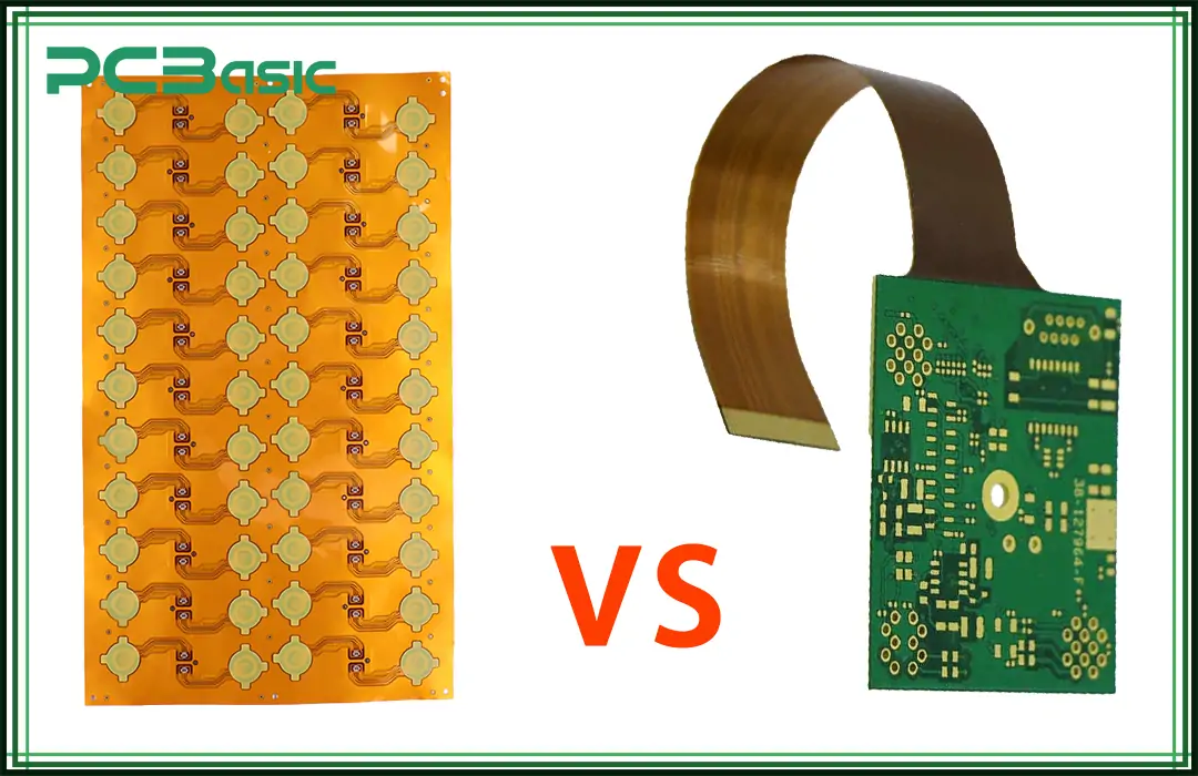
Flex PCBs are a type of circuit board that is designed to bend and fold without breaking and are capable of bearing mechanical stress. Flex PCBs do not have a rigid part. They are primarily used in wearable electronics such as smart watches and earphones, where space constraints are essential design parameters.
Rigid-flex printed circuit boards are a type of PCB technology that is designed to benefit from both flexible and rigid substrate PCB technologies. This means that these boards have one rigid part and the other part is flexible and can easily be bent or flexed. Rigid-flex PCBs are widely used in applications such as medical, satellite communication, military, and aerospace industries where space, reliability, durability, and flexibility are essential design constraints.
Flex PCBs are circuit boards that can be bent and folded without being damaged. Flex circuit boards are primarily used to attain lightweight, flexible, and compact designs that can also withstand extreme environmental conditions and endure vibrations. Typical applications of flex PCBs are smartwatches, earbuds, and smart clothing.
|
Feature |
Rigid-flex PCBs |
Flex PCBs |
|
Flexibility |
Flexible in specific sections |
Fully Flexible |
|
Complexity |
Highly Complex Designs |
Less Complex Designs |
|
Reliability |
High |
Moderate |
|
Space Efficiency |
Excellent |
Moderate |
|
Durability |
Highly Durable |
Moderately Durable |
|
Applications |
Medical, aerospace, defense, consumer electronics |
Wearable electronics, connectors |
In conclusion, rigid-flex circuit boards offer flexible, reliable, and lightweight design solutions for a wide range of applications. Rigid-flex PCB's unique features make them ideal for medical, aerospace, telecommunication, satellite communication, consumer electronics, and defense applications. The choice to choose rigid-flex PCB for your project largely depends on the type of applications and design parameters under consideration. Therefore, understanding rigid-flex PCB is essential for design engineers to make well-informed decisions for their design products.

Assembly Enquiry
Instant Quote
Phone contact

+86-755-27218592
In addition, we've prepared a Help Center. We recommend checking it before reaching out, as your question and its answer may already be clearly explained there.
Wechat Support

In addition, we've prepared a Help Center. We recommend checking it before reaching out, as your question and its answer may already be clearly explained there.
WhatsApp Support

In addition, we've prepared a Help Center. We recommend checking it before reaching out, as your question and its answer may already be clearly explained there.
