Global high-mix volume high-speed PCBA manufacturer
9:00 -18:00, Mon. - Fri. (GMT+8)
9:00 -12:00, Sat. (GMT+8)
(Except Chinese public holidays)
Global high-mix volume high-speed PCBA manufacturer
9:00 -18:00, Mon. - Fri. (GMT+8)
9:00 -12:00, Sat. (GMT+8)
(Except Chinese public holidays)
HomePage > Blog > Knowledge Base > Ground Symbols: Earth, Chassis, Virtual, Analog and Digital
Grounding is one of the most fundamental concepts in the field of electricity and electronics. Whether it is laying out simple circuits or overseeing very complicated industrial processes, an understanding of ground connections is necessary to keep everything safe, stable, and performing as expected.
Ground symbols represent different grounding points in electrical systems. They are used to denote earth ground, chassis ground, virtual ground, analog ground, and digital ground in circuit diagrams. These different types of ground connections help define the electrical reference point, enhance safety, and prevent signal interference.
Different ground symbols are there for different purposes. For example, an earth ground symbol provides a direct connection to the Earth, while a chassis ground symbol is used for safety in electronic enclosures. Understanding these symbols is crucial for engineers and technicians.

What is ground in a circuit? Ground, in essence, plays a fundamental role in ensuring safety, functionality, and reliability in the field of electrical and electronic systems. Ground is usually defined as the reference point from which the voltages are measured in any electrical circuit. On the contrary, it creates a return path for current and hence also becomes the safe way to fault currents to avert electrical hazards.
It could be referred to as the zero voltage reference within the electrical system. Most often, it is physically bonded to the earth itself, which is why it is referred to as an earth ground. That way, then stray currents can safely dissipate into the earth without endangering any apparatus or personnel from electric shock.
Grounding reduces electrical noise and thus creates a stable reference for measuring voltages. It also ensures safety. Most of the time, in complex circuits involving the most sensitive of electronics, a precisely defined ground would help reduce the effect of electrical noise and provide a stable reference for measuring voltages.
There are different types of ground, including earth ground, chassis ground, and virtual ground, each playing a role in maintaining electrical balance and stability.
The ground wire is one of the important features of electrical and electronic systems to give safety as well as stability to the designs. The main feature of this core component has to be providing an easy as well as low-resistance path leading to the Earth to discharge the excess or fault currents away from equipment or people.
Ground wires carry many functions. The very prominent role among them is safety against electric shock which is created during faults like short circuits or equipment damage. In such cases, this wire carries the charge of fault current to the ground rather than through a person or any surrounding object. This considerably decreases the chances of an individual getting electrocuted from contact with a device that has failed.
Ground wires also protect electrical equipment and systems. They divert all stray currents from sensitive components and even transient voltages, which they get from power surges, lightning strikes, and contact with live wiring.
Beyond having safety, having a ground wire helps maintain the system right overall: it provides a common reference point for all voltages reducing the chances of fluctuation and proper operation of interconnected circuits.
Faulty ground wires can lead to erratic operation and pose significant safety hazards. The significance of this wire will become even clearer as we venture into various grounds.
Different types of ground serve distinct purposes in electrical and electronic systems. Engineers and technicians use various ground symbols to identify the type of grounding in a circuit. Below are the major ground symbols and their meanings:
The electrical ground symbol used most frequently in schematics represents the common ground in a circuit. This reference point ensures that all components share the same electrical potential.
It shows three superposed horizontal lines stacked vertically, growing thinner toward the bottom. The zero-voltage reference used for measurements and calculations in a circuit is generally that type of ground.

Ground Symbol
The chassis ground symbol carries the meaning of a physical tie to the metallic structure or enclosure of a device. It makes sure that the outer casing of the device remains at a safe potential, avoiding electric shocks.
The symbol looks like a rake with converging diagonal lines. Chassis ground is common in household and industrial appliances, where leakage currents must not be present.
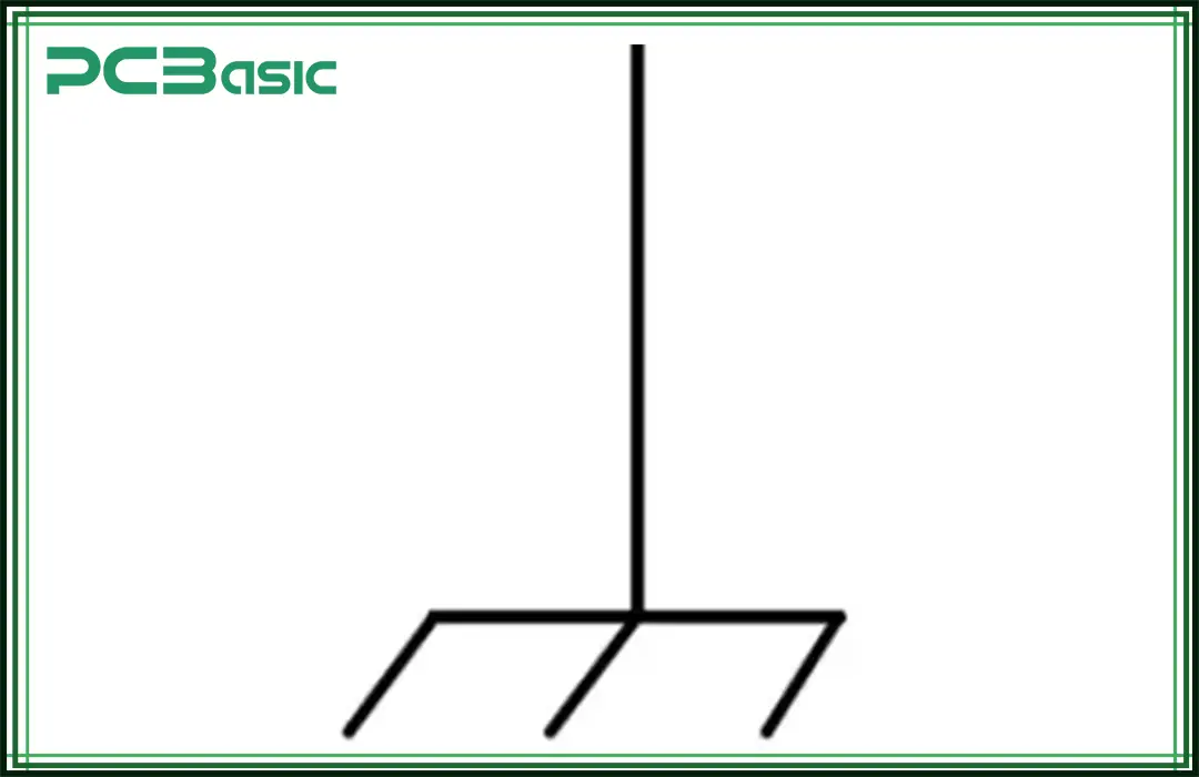
Chassis Ground Symbol
It indicates directly a physical connection to the Earth, which is mostly done by grounding rods or plates that are buried. The earth ground is very important from the safety standpoint, as this gives a direct route for fault currents to dissipate into the earth.
The earth ground is characterized by three horizontal lines of different lengths, stacked vertically and the longest at the bottom, and is widely applied in building wiring and electrical distribution systems.
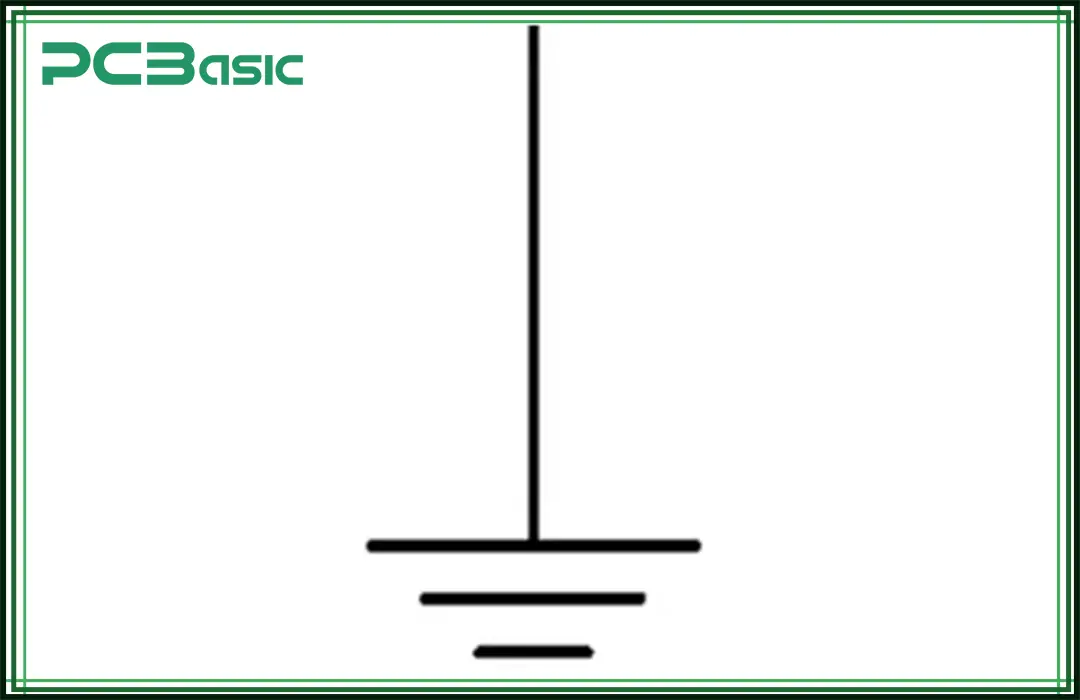
Earth Symbol
In a circuit, a virtual ground is defined as the ground, which is an imaginary ground point created for use in any system that does not connect directly to the Earth. It finds applications for dual power supply circuits wherein it serves as the reference midpoint for positive and negative voltages.
Virtual ground has no universal symbol; it is usually a single horizontal line with a name attached to it, such as "VGND." It is used very frequently in operational amplifier circuits and portable devices.
Analog and digital grounds have specific functions in mixed-signal systems because they will isolate noisy digital signals from sensitive analog signals. This will limit the interference influence and give the most accurate operation to both domains.
Analog ground usually carries the normal ground symbol, while digital ground might, in schematics, have the same label as another label like "DGND." These two grounds will be connected at a single point to avoid ground loop problems while retaining isolation.
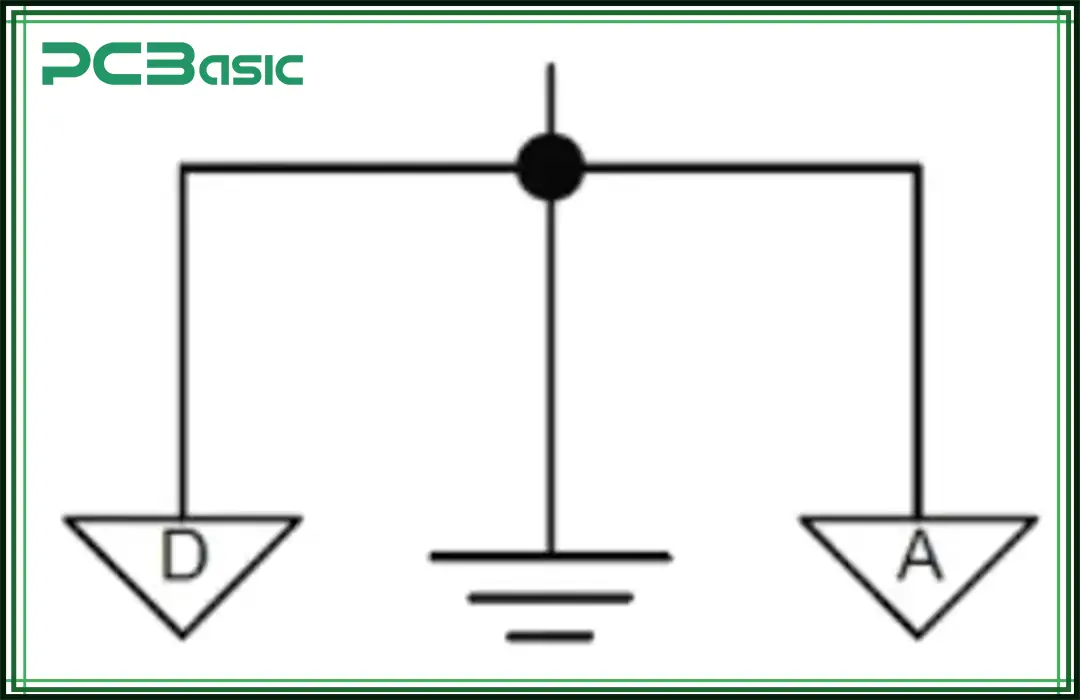
Analog and Digital Ground
Grounding serves as the foundation of secure, reliable, and efficient electrical and electronic systems. Providing reference points at zero voltage and protection from electric shock, grounds are indeed crucial in designing and operating circuits.
The engineer, technician, or hobbyist must understand the different kinds of grounds – earth, chassis, virtual, analog, digital and their symbolic notations as well as each of these kinds have different applications. Some are being used for safety in larger electrical systems, while some are used for dirt reduction in sensitive electronic circuits.
Appropriately applying these principles and symbols will pave the way for good performance in electrical systems and eliminate risks associated with their use. Grounding will thus continue to play the role of the "silent protector" amid the often-boisterous voices of technology.

Assembly Enquiry
Instant Quote





Phone contact

+86-755-27218592
In addition, we've prepared a Help Center. We recommend checking it before reaching out, as your question and its answer may already be clearly explained there.
Wechat Support

In addition, we've prepared a Help Center. We recommend checking it before reaching out, as your question and its answer may already be clearly explained there.
WhatsApp Support

In addition, we've prepared a Help Center. We recommend checking it before reaching out, as your question and its answer may already be clearly explained there.
