Global high-mix volume high-speed PCBA manufacturer
9:00 -18:00, Mon. - Fri. (GMT+8)
9:00 -12:00, Sat. (GMT+8)
(Except Chinese public holidays)
Global high-mix volume high-speed PCBA manufacturer
9:00 -18:00, Mon. - Fri. (GMT+8)
9:00 -12:00, Sat. (GMT+8)
(Except Chinese public holidays)
HomePage > Blog > Knowledge Base > Current Limiting Resistors
The addition of resistors within circuits allows users to regulate electric current flow. A high current level can harm the components inside the system. The current limiting resistor functions to control electric charge movement. This helps protect components from excessive current flow.
A resistor connected in series with other components protects the system from short-circuiting and overcurrent damage. As a result, the resistor maintains a smooth current flow through electrical circuits to protect valuable system components. The resistor dissipates power when electrical circuits encounter component failure.
The guide has all the information about current limiting resistors, including their function and operation. It also explains how this device protects system elements.
Read on.
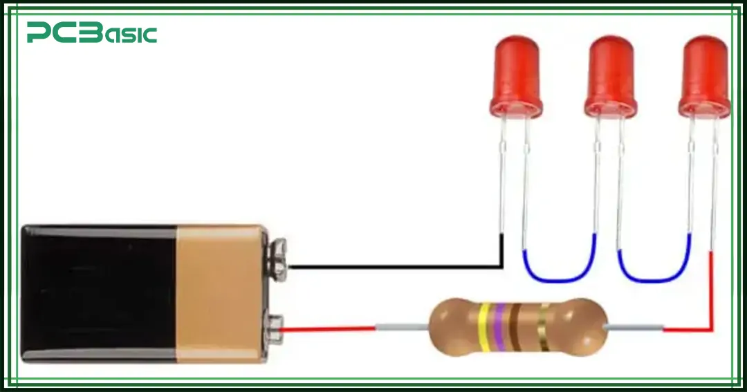
It's one of those components that looks simple—but it does a lot. A current limiting resistor is exactly what it sounds like. It limits current. That's it. But that job is more important than people think.
It's just a standard resistor used in a smart way. You drop it in series with something delicate like an LED or a microcontroller pin, and it keeps the current from getting out of hand.
Without it, even a basic 5V supply can fry your component in seconds.
You will see it everywhere in real-world circuits. Especially where parts can't protect themselves. Things like sensors, ICs, transistors—most of them need help when it comes to current control.
So, this resistor steps in. It takes the hit, drops the extra voltage, and keeps the current right where it should be.
It does not get much credit. But your circuit wouldn't last long without it.
It works according to Ohm’s Law principle. According to this law, voltage directly matches the current level and resistance measurement.
For example, a 5V supply operates an LED which requires only 20mA. When a resistor is absent the LED attempts to draw maximum possible current from its supply. It burns out in seconds.
The addition of a series resistor enables you to regulate current flow.
Here’s how:
1. Subtract the forward voltage of the LED from the supply voltage. Let’s say the LED drops 2V. That means the resistor needs to drop the remaining 3V.
2. Use Ohm’s Law to find the resistance: V=IR or, R = V/I = 3V / 0.02A = 150Ω
Now you know you need a 150-ohm resistor to limit the current to 20mA.
The resistor “takes the hit” by dropping voltage and resisting the flow of excess current.
It’s placed in series, meaning the current must pass through it before reaching the component. That’s how it controls the flow.
If you remove the resistor, the circuit will still work—just not for long. The component will likely fail from overcurrent.

Here’s what it really does in a circuit:
This is the most important job. Components like LEDs, microcontrollers, and FETs have limits. A current limiting resistor makes sure those limits are not exceeded.
Want to dim an LED? Increase the resistor value. Less current means less brightness.
In transistor circuits, resistors help set the bias point. That’s how you control gain and stability.
If you accidentally create a short, a current limiting resistor keeps things from blowing up instantly. It slows down the disaster.
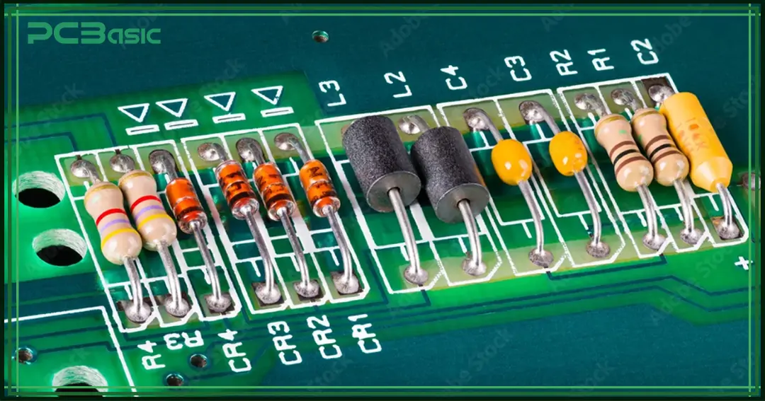
Let’s go over a few real-world examples. Here, we will find out how resistors limit current flow to protect components from overcurrent damage.
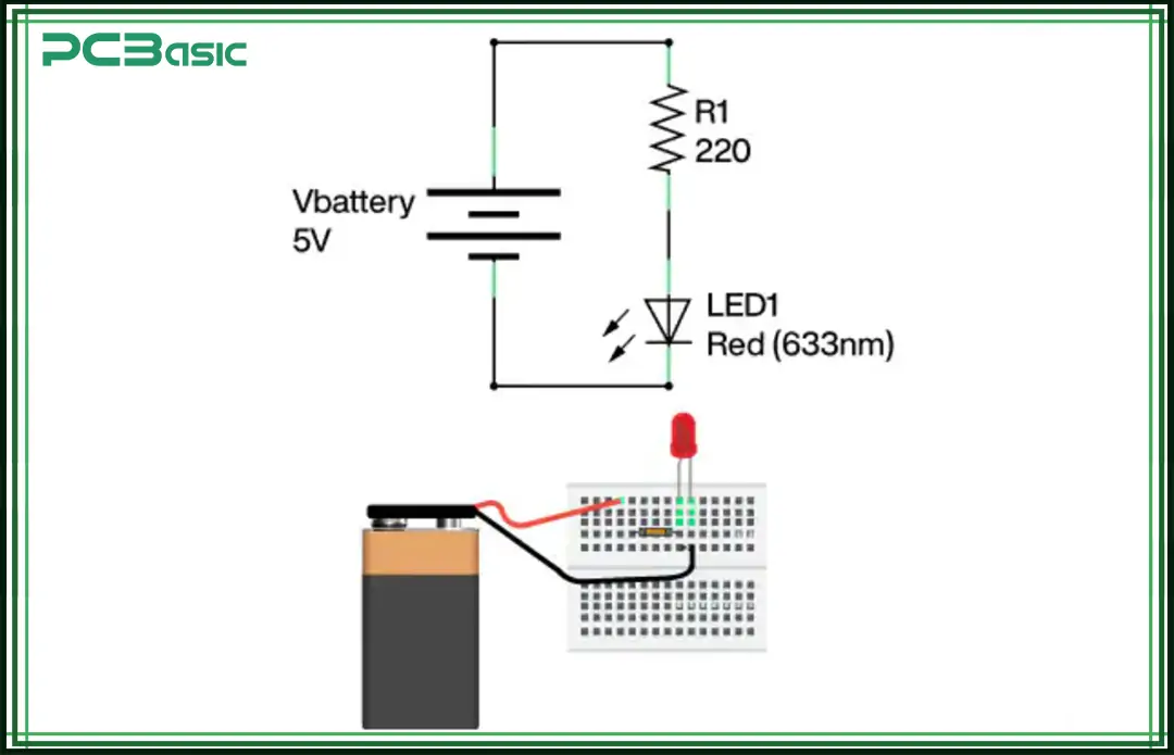
Again, taking the above for example. You have a red LED that operates at a 2V, 20mA. The power supply is 5V.
You need to drop 3V.
R = 3V / 0.02A = 150Ω
So, a 150-ohm resistor will limit the current and protect the LED.
DC motors draw a lot of current, especially at startup. If your supply can’t handle that, things heat up. Or worse, your driver chip smokes.
Using a current limiting resistor helps smooth out that inrush.
Say you’re running a small 6V motor that stalls at 2A, but your control circuit can only handle 1A. You don’t want to cut power entirely—you just want to keep it in check.
Add a resistor in series to limit the startup current, even if only temporarily. It might not run at full speed, but it’ll run safely.
In more advanced designs, this is handled with current-limiting circuits or drivers. But for simple setups? A resistor works fine.
Microcontrollers don’t like surprises. They’re not built to handle big currents—GPIO pins usually max out around 20-40mA.
Hook them up directly to an LED or transistor base without a resistor. You’ll kill the pin. Maybe even the whole chip.
When driving an LED from an MCU, a resistor protects the pin by keeping the current within safe limits.
Even when sending signals to other ICs or transistors, resistors help avoid excessive draw.
It’s all about control. The MCU controls everything—but the resistor makes sure the current behaves.
1. Power supply voltage = 5V
2. Required current for component = 10mA
3. Resistor value = 5V / 0.01A = 500Ω
A 470Ω can be used here to limit the current flowing into the microcontroller pin.
When using a BJT transistor, you apply current to the base to turn it on. But again—too much current, and things go sideways.
A base resistor is essential. It limits how much current flows into the transistor’s base from the microcontroller or other logic source.
Let’s say you’re using an NPN transistor to switch a relay. The relay needs 100mA, and the transistor’s gain (β) is 100.
You need:
I=100mA/100=1mA
If your MCU runs at 5V, then:
R=(5V−0.7V) / 0.001A=4.3k Ω
Use a 4.7kΩ resistor, and you are good. Without it, the pin might try to dump too much current, damaging itself and the transistor.
Refer to the component datasheet to determine voltage drop specifications along with suitable current levels for your LED.
You may check the component by testing it when datasheets are unavailable.
The LED, along with its resistance, gets connected in series to a variable voltage source.
You should start the voltage at 0 volts while increasing it slowly until the LED produces illumination. Take measurements to determine both LED voltage and circuit current.
Consider the LED requires 15 mA while its voltage drop reaches 2 volts. The power source you want to use delivers 5 volts. What value resistor will you need?
The first step to determine the resistor value requires measuring the voltage drop across it. The LED consumes a 2-volt drop so the resistor must experience a 3-volt drop.
The resistor must drop 3V while allowing 15mA to flow through the LED.
The required resistor value can be determined through ohm's law application.
V = R × I
Or, V / I
This gives us:
V / I=3V/15mA
R=200 ohm
So, 200 ohm resistance is required.

The math might be simple. But in practice, a few things often go wrong.
This is more common than you’d expect.
You calculate for 5V, but the board runs on 3.3V.
That mismatch changes everything.
Always confirm the actual supply voltage before choosing the resistor.
Guessing the required current isn’t safe.
Too much, and you risk burning out the component.
Too little, and it won't operate correctly.
Check the datasheet.
Know what your component actually needs.
This one’s easy to miss.
Even if your resistor has the correct resistance, it still needs to handle the power.
Use this formula:
P=I²R
That tells you how much heat the resistor will need to dissipate.
If the number is higher than the resistor's rating, it will overheat.
And when that happens? It may fail silently. Or burn out completely.
So, always choose a resistor with some headroom.
If your power calculation comes close to the limit, go with the next higher wattage.
It's a small step that prevents long-term failures.
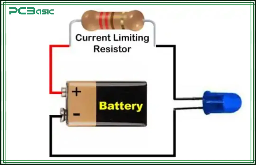
A current limiting resistor calculator is an easy tool to simplify the process. These calculators take the same formula we used earlier but automate the math. You’ll just input your values, and the calculator will provide the correct resistor value.
Here’s how to use it:
Enter Supply Voltage: This is the voltage coming from your power source.
Enter Load Voltage (Forward Voltage): This is the voltage drop across the component (e.g., an LED).
Enter Desired Current: This is the target current for the component, typically given in milliamps (mA).
Once you enter these values, the calculator automatically computes the resistor value in ohms. It will also sometimes provide a recommended power rating for the resistor to ensure it can handle the heat generated by the current flow.
A current limiting resistor might not seem like much. But it’s one of the most important things you’ll use in a circuit.
It protects components. Prevents damage. And helps things run smoothly. From blinking LEDs to complex microcontroller setups—this little part keeps everything in line.
Don’t ignore it or skip it. Use Ohm’s Law or a resistor calculator to choose the correct value and rating.
In electronics, the small component really does matter.

Assembly Enquiry
Instant Quote
Phone contact

+86-755-27218592
In addition, we've prepared a Help Center. We recommend checking it before reaching out, as your question and its answer may already be clearly explained there.
Wechat Support

In addition, we've prepared a Help Center. We recommend checking it before reaching out, as your question and its answer may already be clearly explained there.
WhatsApp Support

In addition, we've prepared a Help Center. We recommend checking it before reaching out, as your question and its answer may already be clearly explained there.
