Global high-mix volume high-speed PCBA manufacturer
9:00 -18:00, Mon. - Fri. (GMT+8)
9:00 -12:00, Sat. (GMT+8)
(Except Chinese public holidays)
Global high-mix volume high-speed PCBA manufacturer
9:00 -18:00, Mon. - Fri. (GMT+8)
9:00 -12:00, Sat. (GMT+8)
(Except Chinese public holidays)
HomePage > Blog > Knowledge Base > PCB Button: An Ultimate Guide
Have you ever wondered how the tiny switches let you turn on your smartphone? How does a touch panel turn on and off your room lights? If so, you are at the right place.
Presenting an Ultimate guide to explore the world of PCB buttons!
PCB buttons are small yet powerful devices that enable users to interact with electronics inside every modern device. This article will develop a clear understanding of PCB buttons, their types, and most importantly, how and which type to integrate in your product.
This guide about PCB buttons is well-justified for electronics designers, product engineers, and hobbyists who are simply curious about how PCB buttons work! Let's make your next project a pro level!

A PCB (Printed Circuit Board) button is a kind of user interface device that provides on/off or command control input to any electronics system. A user just physically Presses or Touches a button; beneath that is some transducer action that generates a corresponding signal for a backend microcontroller or a control circuit. This simple-looking action does everything from controlling a television to cruising an airplane. A PCB button may be referred to as an electromechanical switch or a transducer, which is generally mounted on a printed circuit board. For a simple example, let's assume the user is an actuator, with the underlying mechanism as conductive pads on the PCB. The user is completing a circuit. When released, the switch returns to the default state, hence opening the circuit again as it was in its initial form. The reliability of this button is very crucial. Any malfunction or no response can make your product useless or unsafe.
Human - Machine Interaction
PCB button provides an ultimate way for end users to communicate with the engineering system. A user's trigger is followed by controlled actions to control even a flying jet!
Precise Control
A PCB button can provide a single pulse or a set of time-bound pulses to lock/unlock any device, like refrigeration controls. PCB button is the only device which enabled the feature of press and hold command in modern consumer electronics.
Tactile Feedback
Modern PCB buttons also offer tactile feedback to reassure a user that the input has been registered.
Safety and Reliability
Medical and automotive industries heavily depend on reliable PCB buttons. Designers need to make sure that even if the button fails, there must be no major product failure.
Key Benefits
1. Versatile: PCB buttons are now found in every modern electronic product, from smartwatches to industrial automation.
2. Cost Effective: Standard PCB switches are low in cost and inexpensive to manufacture. They can be easily integrated into several consumer goods.
3. Durability: High-quality PCB buttons can bear millions of presses.
4. Reduced PCB Footprint: The latest PCB buttons you see in smartphones and wearables have a minimal footprint making our gadgets more compact.
PCB buttons are available in different sizes, shapes and feedback styles. You must choose the right type for your electronic product. The decision is based on many factors like environment, cost, reliability and ruggedness. Let's highlight the different types of PCB buttons below.
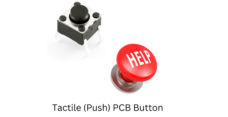
A Tactile PCB button has a small metal or polymer dome-like structure, which collapses when pressed. Tactile PCB buttons produce an audible click-like sound and tactile feedback. Such a mechanism confirms to the user that the button is pressed without requiring a user to look at the screen or any LED indicator. Tactile switches are generally common in user interfaces that feature real-time feedback, like push-button control panels or mechanical keyboards. Tactile switches offer the following features.
1. Highest Reliability: Tactile switches may last more than 100,000 presses or even more.
2. Reassurance: Tactile sensation avoids accidental presses.
3. Compact in Size: They fit on small PCBs. Hence ideal for handheld devices.
Mostly the tactile switches follow a normally open configuration. Once you press it, it closes the circuit. Upon release, the circuit opens once again. These switches are the first choice for professional equipment as they offer physical confirmation of the command.
Non-tactile PCB buttons are flat switches. They do not produce any audible clicks. They have lower tactile feedback but are very robust. They offer smoother actuation. Non-tactile switches are popular where quiet operation is required. The following equipment may contain such switches.
1. Healthcare Equipment
2. Kitchen Equipment
3. Laboratories
4. Gadgets
These switches are often incorporated with visual or audio alerts like LEDs or beeps.
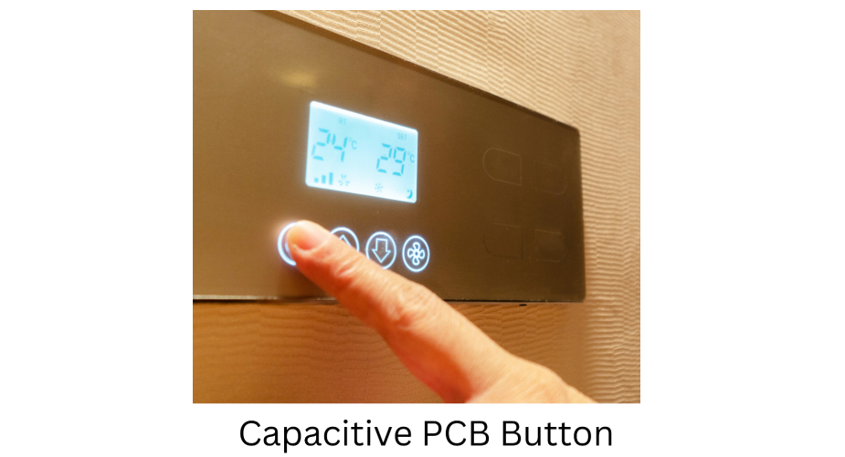
Capacitive touch PCB buttons are very common in smartphones, smart home panels and automotive touch panels. Such a button detects any change in capacitance when a finger or a conductive object touches the sensor area. Capacitive touch buttons are a type of solid-state device, it does not have any moving parts.
Such buttons have integrated proximity-sensing features to wake up and illuminate the sensor area before any physical contact. On the downside, capacitive buttons are susceptible to false triggers. They are not preferred in challenging outdoor or industrial environments.
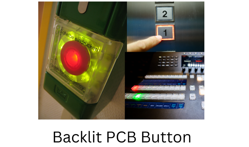
LED Backlit PCB buttons have an integrated feature of illumination. Their working principle can be of any type; they may be capacitive, tactile or non-tactile, but the main component is a light-emitting diode along with the actuator.
This backlighting is generally required in automotive dashboards and cockpit instrument panels. Moreover, aesthetic gadgets like nightlights and alarm clocks have these buttons. Gaming consoles also offer vibrant and customizable color schemes.
Backlit buttons enhance the appearance of modern products, especially when LED color changes from single color to RGB arrays. Manufacturers also insert translucent caps or plastic diffusers to spread the light in the surroundings.
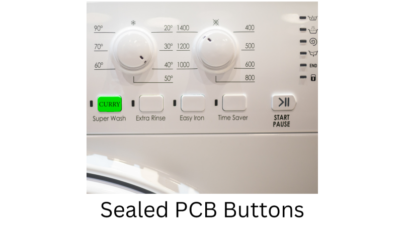
Sealed PCB buttons have shielded internal contacts. Hence dust, moisture, or any contaminants can't reach inside. Washing machines and microwave ovens do have shielded PCB buttons. In general, these buttons are best fit for outdoor, marine and food processing equipment.
Buttons are often sealed using O-rings, gaskets or special long-lasting rubber membranes. Sealed PCB buttons may be rated up to IP67.
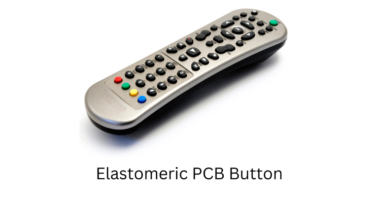
Elastomeric PCB buttons are very common in television and air conditioner remote controls. They have a silicone rubber-like appearance to offer a soft and cushioned press. Tactile response is soft and cushioned.
They are manufactured with custom colors and characters. Icons are generally printed or laser-etched over the surface. Elastomeric PCB buttons are visually intuitive.
Metal dome PCB switches offer high tactile feedback. Such buttons have metal discs or a plate housing. They produce crisp clicks when pressed. Metal dome PCB buttons are very common in ATMs and gas pump interfaces. Such buttons are also very popular in high-end industrial keyboards where tactile feedback is very important.
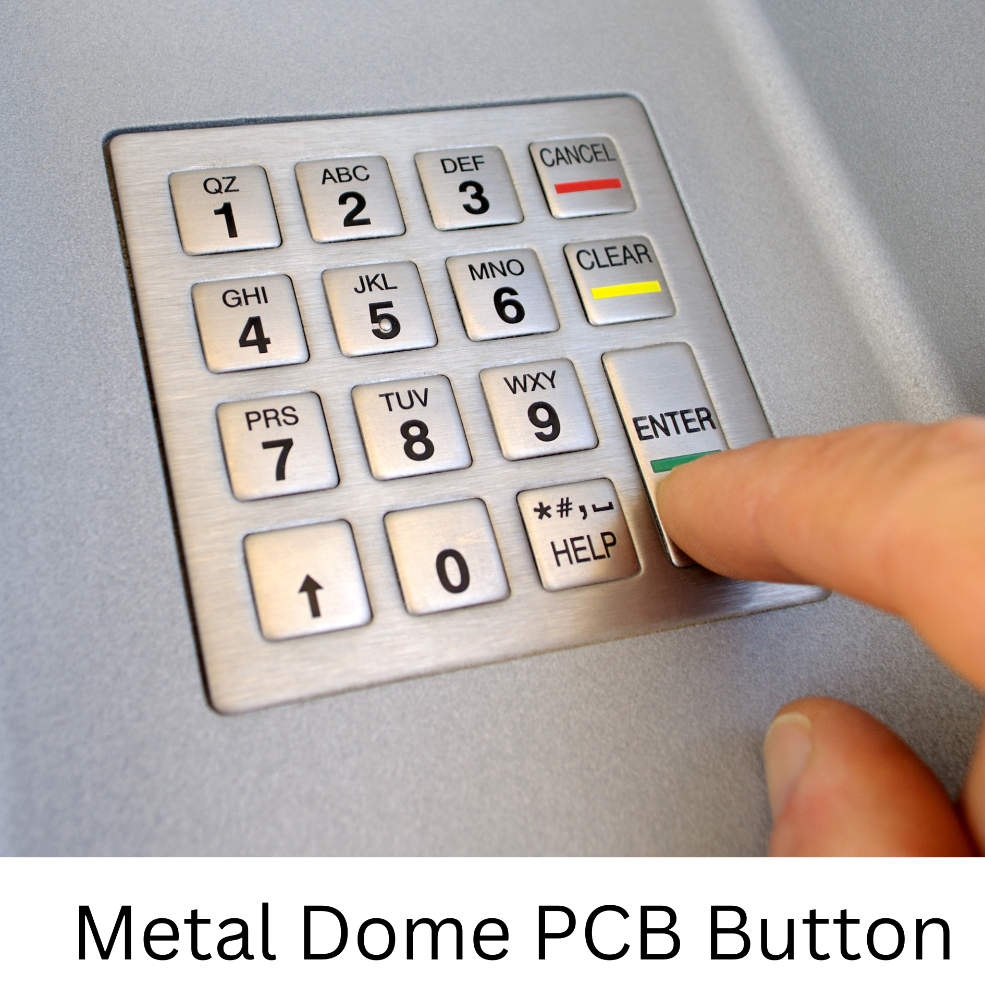
Metal domes PCB buttons offer a versatile range in actuation force, starting from light (100 - 150 g) to heavy (250 + g).
A PCB button works more like a mechanical switch. Mounting the switch directly on a PCB evolves several design and manufacturing aspects which are highlighted below:
How does a Circuit Complete?
1. Whatever the type, when a button is pressed, the PCB circuit changes its state from 0 to 1 or vice versa. How to handle this is important.
How will a Signal be Transmitted?
1. It is important to consider how the current flows will trace toward the microcontroller or any control circuitry. How the controller will read the change and execute the corresponding function.
How to Return to the Default State?
1. It is important to study how the switch should return to its original state. i.e., how to break the electrical connection.
How Tactile Feedback Works?
Here, we have two aspects: physical and perceptual.
1. Physical Feedback: The dome deforms under pressure in the case of tactile switches. This deformation provides a snap and a click-like feeling.
2. Perceptual Feedback: The audible click assures the user that the switch has been activated.
How Does Capacitive Touch Work?
Here we have a capacitive transducer. The following factors are of key importance here:
1. Change in Capacitance: The human finger is slightly conductive. When it reaches near or touches a capacitive sensor pad, the local electric field is altered, hence changing the pad's capacitance.
2. Output of a sensor fed to Controller: A microcontroller is present which monitors the pad's capacitance. Upon significant change, it interprets that the as a button is pressed.
3. Solid State Button: Capacitive PCB buttons do not have moving parts. Hence no mechanical wear but false triggering must not be overlooked.
PCB button plating is the application of a thin metallic layer like gold, silver, or nickel onto the contact pad or dome surface. This plating ensures high and consistent electrical conductivity and prevents contact from any environmental damage.
To Enhance Conductivity
1. Metals like gold have low contact resistance, generating a stable and cleaner signal. This feature is required in very low-voltage circuits or where a small resistance can cause errors or significant power loss.
To Enhance Durability
1. The button press is nothing but friction. Hard and corrosion-resistant plating enhances the durability of a PCB Switch.
2. To provide Resistance against Corrosion, plating avoids Oxidation or Tarnish on contacts. Hence, signal disruption is prevented.
Smoother Actuation
1. Plating, especially a polished one produces smooth movement which can improve tactile feel and lower the friction in dome-based switches.
Let's discuss why Button Platting is Crucial. It is required for the following objectives:
Impedance Control
1. For high-frequency digital circuits, materials like ENIG (Electroless Nickel Immersion Gold) offer stable impedance. This is done to prevent signal mismatches and signal distortions.
Dynamic Flex
1. In wearables and foldable devices, PCBs often bend during use. Plating ensures that the copper traces and contacts do not crack or lose conductivity.
The following materials are generally used for PCB Buttons Platting.
1. Gold Plating
2. Highest Conductivity and corrosion resistance.
3. Expensive but superior performance.
4. Silver Plating
5. Best conductivity.
6. Prone to tarnish when exposed to humidity or sulfur.
7. Cost-effective.
8. Tin Plating
9. Lowest cost and easy application.
10. Acceptable conductivity but less durability than gold or silver.
11. Very Common in consumer electronics.
12. Nickel Plating
13. Used to improve adhesion and wear resistance under any other coating.
14. Provides hardness and longevity.
Manufacturing a high-performing PCB button is not the only requirement. Engineers have to balance material choice, mechanical requirements and layout constraints. User experience is above all. Let's discuss the key factors for turning a simple switch into a robust and user-friendly switch.
Conductive Materials
1. Copper is the first choice for PCB trace due to its high conductivity and easy etching. For the contact plating, gold or nickel are reliability choices.
2. Substrate Material
FR4: used in most rugged PCBs.
Polyimide: Ideal for Flexible PCBs
Actuator Materials
The button's actuator may be a rubber dome a plastic plunger or some metal disc. It must withstand repeated presses without deforming. Silicone elastomers may be used for comfort and durability.
Contact Pad Design
It must be carefully sized. If the pads are too small, it will lead to mechanical misalignment causing missed presses.
Signal Integrity
Accurate impedance is required in high-frequency RF or high-speed data systems. Trace widths and distances must be accurately calculated.
Grounding and Shielding
Grounding is crucial to avoid any signal noise. Ground planes must be deployed beneath or around the button's circuit. Shielding is also required for capacitive touch buttons.
Debouncing
Mechanical switches may bounce for a few milliseconds when pressed. It can create multiple on/off signals. Designers need to address this by adding a small RC circuit in the hardware or some sort of debouncing routine in firmware.
Button Mechanism
Tactile feedback is often based on a metal or a polymer dome. The geometry, thickness, and material properties pronounce this feedback.
Actuation Force
This force is ideal and satisfactory for perception. The range is as follows:
1. Light (100–150 g): Remotes and handheld electronics.
2. Medium (150–250 g): Consumer keyboards, general-purpose buttons.
3. Heavy (250+ g): Industrial control panels.
User Experience
For general consumer devices, a snap-like feel enhances perceived quality. Specialized equipment may demand a subtle press to minimize noise or operator strain.
LED Integration
Single-color or RGB LEDs are placed beneath or around the button for illumination.
Light Diffusion
Designers also incorporate translucent caps or silicone layers to diffuse the light hence preventing hotspots and creating a uniform backlighting.
Power Management
LED backlighting increases power consumption; hence, efficient LED drivers, possibly based on PWM dimming, are preferred.
Shape and Size
Buttons may be round, square, rectangular, or custom-shaped. Ergonomics need to be considered.
Labeling and Icons
Icons, symbols or alphanumeric are Printed or laser-etched to guide the users. Negative Backlit buttons may be used to light up the symbol only.
Color Variations
Multicolored arrays or translucent plastics allow for brand-specific aesthetics or color-coded functional groups (e.g., red for emergency stops, green for a start).
Sealing and Waterproofing
Gaskets or membranes are integrated for IP-rated designs. This is critical in devices which operate in harsh environments.
Compactness
PCB space is precious when you talk about miniaturization. Buttons need to be carefully dimensioned and placed.
Spacing
If buttons are too close, one might accidentally press multiple buttons at once. You must provide sufficient spacing.
Mechanical Integration
The button must be aligned with an external housing or a frame. Designers generally add mechanical support structures like plastic pillars to ensure consistent actuation.
|
Criteria |
Design Considerations |
|
Choice of Material |
Must use high-conductivity conductors like copper, gold or nickel for plating. Choose FR4 or any flexible substrates. Actuator materials must be able to endure repeated presses. |
|
Circuit Layout |
Ensure proper sizing of the contact pad, consider debouncing and provide grounding and proper shielding. The circuit must maintain signal integrity for high-speed circuits. |
|
Tactile Feedback |
Select the desired click mechanism based on the application. Use a metal or polymer dome. Must consider actuation force and user preferences. |
|
Backlighting |
You may Integrate LEDs for visibility. Apply diffusers for uniform light spread but try to manage power consumption. |
|
Customization |
Aesthetic shapes, sizes and labels may be designed for branding or ruggedization. Do not oversight proper sealing options. |
|
Size & Integration |
Ensure that the button fits into the PCB housing. Consider proper spacing requirements and alignments along with mechanical constraints. |
|
Environmental & Lifetime |
PCB buttons must be tested across various temperature and humidity ranges. Cycle ratings must be verified and aligned with user demands. |
In today's digital age, we cannot imagine human-machine interaction without PCB buttons. In this article, we have discussed several types of PCB buttons and, most importantly, how a PCB button works.
Although PCB buttons appear simple their construction and the science behind selecting the most suitable PCB for your product are very crucial to your product's success. Engineers must consider reliability and robustness as their prime objective. Mechanical constraints and cost also add complexity to our selection. Proper selection of a PCB button can make or break your product. Careful electric circuitry behind your PCB button is very important. It involves a thoughtful process.
If you're looking to refine or innovate your product's user interface, our team is ready to help you. We are specialists in PCB button design, from concept to final production. Leverage our expertise in mechanical, electrical, and interface design and make each press of your product's button a ladder of success. Let's work together to turn your visions into reality. Rightly placed and carefully engineered button at a time.

Assembly Enquiry
Instant Quote
Phone contact

+86-755-27218592
In addition, we've prepared a Help Center. We recommend checking it before reaching out, as your question and its answer may already be clearly explained there.
Wechat Support

In addition, we've prepared a Help Center. We recommend checking it before reaching out, as your question and its answer may already be clearly explained there.
WhatsApp Support

In addition, we've prepared a Help Center. We recommend checking it before reaching out, as your question and its answer may already be clearly explained there.
