Global high-mix volume high-speed PCBA manufacturer
9:00 -18:00, Mon. - Fri. (GMT+8)
9:00 -12:00, Sat. (GMT+8)
(Except Chinese public holidays)
Global high-mix volume high-speed PCBA manufacturer
9:00 -18:00, Mon. - Fri. (GMT+8)
9:00 -12:00, Sat. (GMT+8)
(Except Chinese public holidays)
HomePage > Blog > Knowledge Base > How to Use a Multimeter?
A multimeter is a versatile and very important device for those working in an electrical environment. The multimeter can measure the most important electrical characteristics like voltage, current, and resistance.
To measure any value on a multimeter all we need is to connect leads to the multimeter select the desired characteristic with a rotating switch and then measure in the correct order. Whether we’re measuring important values in the circuit, troubleshooting or testing a multimeter can always be the most important thing in the work.
A multimeter is a handheld device that is used to measure values in circuits like current, voltages, and ohms. Not just measuring values, a multimeter is one of the most important devices in testing and fault detection as well. A multimeter is one of the most essential things in electrical engineering. It is the most essential tool for professionals in the field of electrical and electronics engineering.
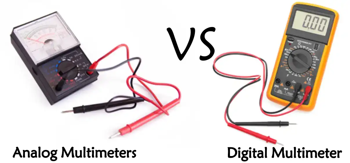
Multimeters have two basic forms, which are analog and digital multimeters.
Analog Multimeters: This type of multimeter utilizes a needle and a scale to show readings. They are not as widely used today, yet there are still certain applications where the visual representation of fluctuations is very useful.
Digital Multimeters (DMM): These are the most commonly used and user-friendly multimeters. They display values using digital numerical values on an LCD and/or LED screen and offer more accurate readings. Many digital multimeters can also measure values like capacitance, frequency, temperature, and more.
Multimeters have many applications from measuring voltages, and currents to figuring out faults in circuits and doing testing they are used everywhere in electrical engineering.
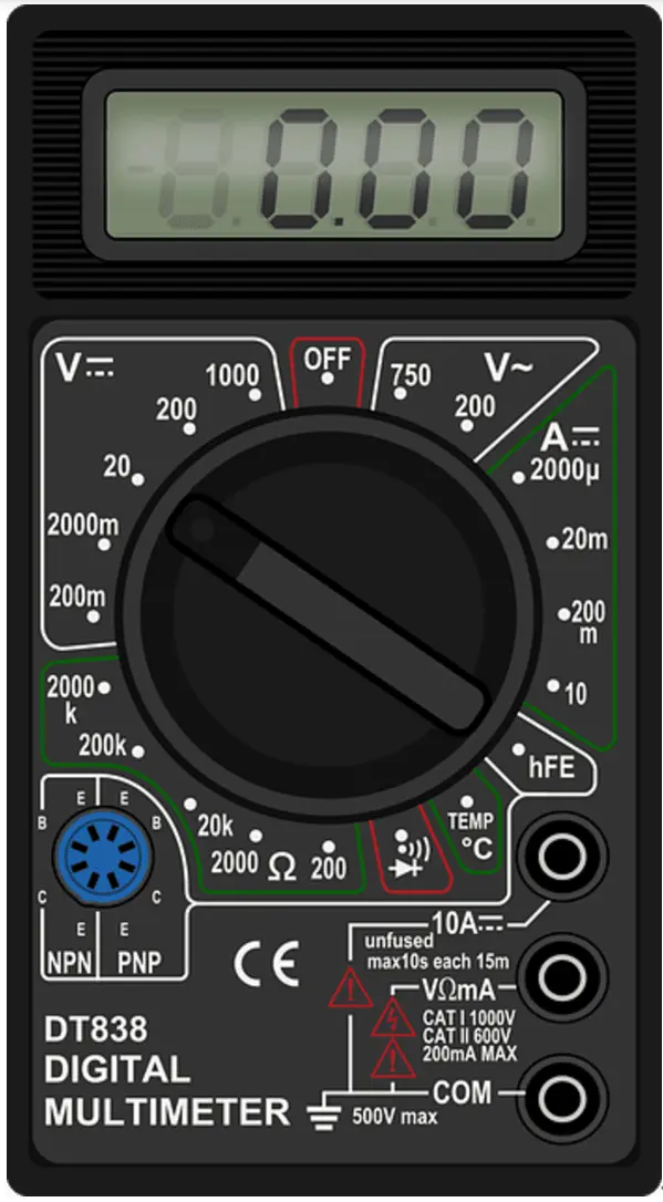
Multimeters use a bunch of important symbols to represent different measurement modes and functions. To use devices correctly and safely we must get familiar with these symbols. Here are some of the common symbols that can be found in a multimeter:

Voltage Symbols
● V⎓ (DC Voltage): Measures direct current (DC) voltage, like in batteries or DC circuits.
● V~ (AC Voltage): Measures AC voltage in the circuit, like in household appliances or AC circuits.
Current Symbols
● A⎓ (DC Current): Measures DC in a circuit.
● A~ (AC Current): Measures AC in a circuit.
● mA or µA (Milliamps or Microamps): Use to measure small currents like in micro and mini.
Resistance Symbol
● Ω (Ohms): Measures resistance in a circuit or component.
Continuity Symbol
● )))) or Wave Icon: figures continuity testing in a circuit, ensures our circuit is complete. The multimeter will beep or make a sound if there is continuity.
Diode Test Symbol
● ⎓►|: Used to test diodes and check their forward voltage drop.
Capacitance Symbol
● F (Farads): Measures the capacitance of capacitors.
Frequency Symbol
● Hz (Hertz): Measures the frequency of the AC signal.
Temperature Symbol
● °C or °F: Measures a temperature using a compatible temperature probe.
Common Ground Symbol
● COM: Indicates the common port where the black test lead is connected.
Range and Function Symbols
● Auto-Ranging (AUTO): This indicates that the multimeter automatically selects the measurement range.
Hold (HOLD)
● It Freezes the current reading on the display.
Min/Max
● Records the minimum and maximum values during measurement.
Safety Symbols
● CAT Ratings (CAT I, CAT II, CAT III, CAT IV): Indicates the multimeter’s safety rating for different electrical environments.
Double Insulation (⏚)
● Indicates the device is double-insulated for added safety.
How to choose the right multimeter will depend not only on your specific needs and budget but also on what kind of electrical work you plan to do. Below are some important points that one needs to pay close attention to before purchasing a multimeter:
Type of Multimeter
● Analog Multimeters: Great for those who prefer a live visual representation of readings, like checking fluctuations in voltage or current. It may be a bit difficult to read because of the lack of precision compared to the digital models.
● Digital Multimeters (DMM): These are the most preferred option because of their great accuracy, ease of use, and additional features.

Measurement Capabilities
You must have to ensure the multimeter can measure the basic electrical properties: voltage (AC/DC), current (AC/DC), and resistance.
If you need a DMM with additional measurement options you can look for models that can measure capacitance, frequency, temperature, and duty cycle. Several modes can vary depending on the model you are selecting.
Accuracy and Resolution
Accuracy signifies how closely a reading from the multimeter will correspond to the actual value. Usually, an accuracy level of ∓1% is adequate for general use.
Resolution indicates how finely a multimeter displays its measurements. Higher resolution translates into being better for fine work.
Safety Ratings
Do check out this one, too: the CAT rating of the multimeter. That is a way of stating whether the equipment is safe or can handle the voltage levels:
● CAT I: Low-voltage electronics.
● CAT II: Household appliances and outlets.
● CAT III: Building wiring and distribution boards.
● CAT IV: Utility connections and outdoor wiring.
Choose the CAT that goes along with your working environment.
Standards of Construction and Durability
Since you are going to use the multimeter in all possible rugged works or industrial uses, then you have to look for a sturdy design that supports an ergonomic grip and protects the casing.
Additional Features
The auto-ranging feature is that the selection of the measurement range is done automatically and it makes life easy.
Backlit Display
It works well in the dark place.
Data Logging
Record measurements and analyze them over time.
True RMS
Reading accurate for non-sinusoidal AC waveform.
Budget
The multimeters are classified as being super cheap or expensive, high-tech, and professional. Fix a budget and choose the multimeter that best fits into your budget as well as having more to offer.
These are the best criteria by which you can make the best choice of multimeter for you in terms of reliability, safety, and suitability to your specific requirements.
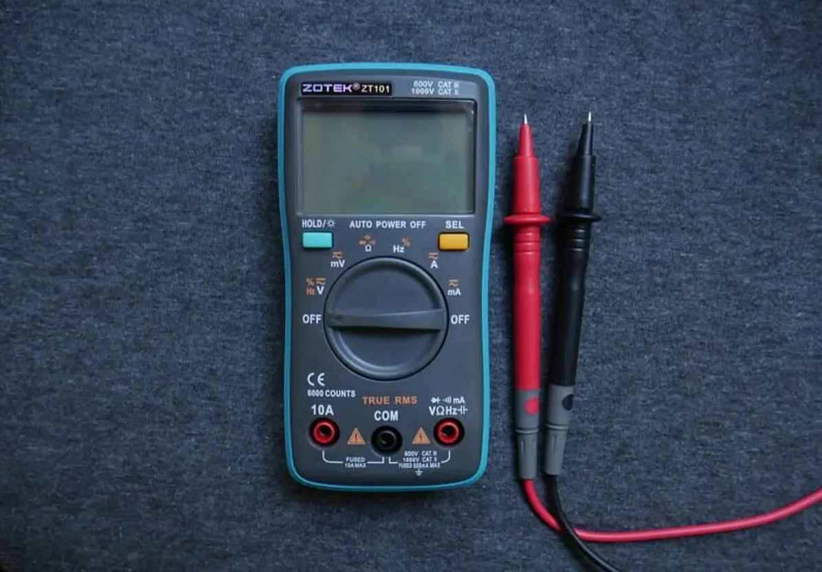
Knowing the various parts of a multimeter will help in understanding how best to use it safely. While the construction would vary somewhat between analog and digital models, most multimeters share some common key components:

Display
● Digital Multimeters: Displays numerical readings by making use of an LCD or LED screen with the indication of backlight in some models for better visibility in lesser light conditions.
● Analog Multimeters: Comprise a graduated scale and a small needle for reading measurements.
Selection Knob (Dial)
This rotating switch allows us to select the desired type of measurements like the voltage, current, resistance, and range. It is simpler with auto-ranging multimeters because the range is automatically selected by the device.
Ports (Input Jacks)
Multimeters contain several input jacks where the test leads are connected. The most common ports are:
● COM (Common): The black test lead is always plugged into this port.
● VΩmA: Used to measure voltage, resistance, and small currents (usually up to 200 mA).
● 10A (or 20A): It is used to measure high currents (usually up to 10 or 20 amps).
Test Leads (Probes)
These wires are tipped with sharp points connecting the multimeter to the circuit or the component test. Positive measurement connection for the red lead, routine or ground connection for the black lead.
Function Buttons
Many digital multimeters include buttons to toggle between functions, such as:
● Hold: Freezes the current reading on the display.
● Range: Manually selects the measurement range (on non-auto-ranging models).
● Mode: Switching between AC/DC measurements and some other modes, such as capacitance or frequency.
Battery Compartment
From that place, the battery is fed to the multimeter. Some models may additionally include their fuse in this section to give overcurrent protection.
Fuse
Normally, By excess current damage protection by the fuse. When it blows, it will stop the working of the multimeter.
Probe Tips
Metal ends of test leads that make contact with the circuit or component. Some probes have removable tips or alligator clips for hands-free testing.
Case and Housing
Multimeter outer casings generally have durable plastic or rubber protection from physical damage and electrical shock.
Stand (Kickstand): Some multimeters have a folding stand to support the device in viewing the display without hands.

A multimeter is the most useful device for diagnosing and troubleshooting electrical circuits. Let’s walk through the basic steps for measuring voltage, resistance, current, and continuity.
Voltage is the potential difference between two points in a circuit and is measured in volts (V). Here’s how to measure voltage using a multimeter:
● Set the Multimeter: Turn the selection knob to the voltage setting. Choose AC voltage (V~) for alternating current (e.g., household outlets) or DC voltage (V⎓) for direct current (e.g., batteries).
● Connect the Test Leads: Insert the black lead into the COM port and the red lead into the VΩmA port.
● Take the Measurement: Touch the black probe to the negative side or ground of the circuit and the red probe to the positive side. For AC voltage, the polarity doesn’t matter.
● Read the Display: The multimeter will show the voltage reading on the screen. If the reading is negative (for DC), it means the probes are reversed.
● Safety Tip: Always ensure the circuit is powered off before connecting the multimeter, especially when measuring high voltages.
Resistance is the opposition to the flow of current and is measured in ohms (Ω). Follow these steps to measure resistance:
● Set the Multimeter: Turn the selection knob to the resistance (Ω) setting. If your multimeter is not auto-ranging, select an appropriate range.
● Connect the Test Leads: Insert the black lead into the COM port and the red lead into the VΩmA port.
● Take the Measurement: Ensure the circuit or component is powered off and disconnected. Touch the probes to the two ends of the resistor or component.
● Read the Display: The multimeter will display the resistance value. If the reading is “OL” (overload), the resistance is too high for the selected range.
Note: Avoid touching the probe tips with your fingers, as this can affect the accuracy of the reading.
Current is the flow of electric charge and is measured in amperes (A). To measure current:
● Set the Multimeter: Turn the selection knob to the current setting. Choose AC (A~) or DC (A⎓) based on the circuit. For small currents, use the mA or µA range. For larger currents, use the 10A or 20A range.
● Connect the Test Leads: For small currents, insert the red lead into the VΩmA port. For larger currents, use the 10A port. Always connect the black lead to the COM port.
● Take the Measurement: Break the circuit and connect the multimeter in series. This means the current must flow through the multimeter. Touch the black probe to the negative side and the red probe to the positive side.
● Read the Display: The multimeter will show the current reading. If the reading is negative (for DC), it means the probes are reversed.
● Safety Tip: Never connect the multimeter in parallel when measuring current, as this can damage the device.
Continuity testing checks if a circuit is complete and allows current to flow. It’s useful for identifying broken wires or faulty connections. Here’s how to test continuity:
Set the Multimeter: Turn the selection knob to the continuity setting (usually indicated by a diode or sound wave symbol).
Connect the Test Leads: Insert the black lead into the COM port and the red lead into the VΩmA port.
Take the Measurement: Touch the probes to the two points you want to test. If the circuit is complete, the multimeter will emit a beep and display a low resistance value (close to 0 Ω). If the circuit is open, the multimeter will show “OL” (overload) and no sound will be emitted.
A multimeter is an essential device for any user dealing with electricity: be you a trained professional electrician, an engineer, or a DIYer. Understanding the components, choosing the right model according to your needs, and mastering a few basic measurements that include voltage, resistance, current and continuity will give you the confidence to diagnose and troubleshoot several electrical problems.
Remember to always prioritize safety; choose the best CAT rating make sure that circuits are not energized when necessary and use proper measurement techniques. The more you practice, the more you'll get used to the multimeter. As a result, it simplifies a variety of electrical work for you. You may need to test a battery, check a circuit, or repair an appliance, and the multimeter comes in handy for the test.

Assembly Enquiry
Instant Quote
Phone contact

+86-755-27218592
In addition, we've prepared a Help Center. We recommend checking it before reaching out, as your question and its answer may already be clearly explained there.
Wechat Support

In addition, we've prepared a Help Center. We recommend checking it before reaching out, as your question and its answer may already be clearly explained there.
WhatsApp Support

In addition, we've prepared a Help Center. We recommend checking it before reaching out, as your question and its answer may already be clearly explained there.
