
Global high-mix volume high-speed PCBA manufacturer
9:00 -18:00, Mon. - Fri. (GMT+8)
9:00 -12:00, Sat. (GMT+8)
(Except Chinese public holidays)





HomePage > Blog > Knowledge Base > Why a Working Prototype Is Not Enough for Consumer Electronics PCB Assembly
Table of Contents
1. A Working Prototype Answers Only One Part of the Main Question
2. Get Ready for Mass Production Before Consumer Electronics SMT Assembly
3. Stable Consumer Electronics PCB Assembly Depends on Control, Not Just Speed
4. Prototype Readiness Has to Be Proven Before Mass Production
When you build one board, small issues in a prototype build can often be fixed by you easily as you are making it by hand. But during the mass production it is seen that the same small issue can affect thousands of PCBs.
Let’s take an example to understand this! A part may be easy to place by hand but very difficult for an assembly machine to place it correctly. This can result in faulty boards, board replacements, production delays and higher costs, which can significantly reduce your margin.
So, a successful prototype is not always enough. It does not necessarily mean that your mass production will also be accurately good. Your prototype of the circuit board must also be designed in such a way that it results in smooth and accurate mass production.
I will tell you what to check before sending your consumer electronics prototype PCB assembly for volume manufacturing. After all, when you are making thousands of circuit boards, even a small issue can become an expensive problem. Let’s get started!
A prototype has one main work: To show that your circuit works as intended. It does not necessarily mean that it is ready for mass production. But that is only one part of the bulk manufacturing process.
A fully workable prototype answers one question: “Does this work?” It does not answer another important question: “Can a factory make this thousands of times without issues?” That question becomes very important when you move into mass production.
• A prototype proves that your design can work.
• Production proves that the factory can make it work again and again.
These are two different things.
When making a prototype, an engineer or technician may be able to fix small assembly issues by hand. But in the mass production process, machines assemble PCBs very quickly. So, there is a chance that a lot of issues can pop up in it.
Therefore, a design that works 100% once may still be difficult to manufacture thousands of times in the same way.
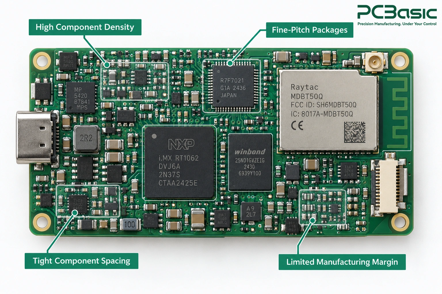
Consumer electronics are usually designed to be small and really affordable. This means placing many parts in a small space on the PCB. Components are close together and the tiny paths that connect them called traces also become smaller.
As everything gets closer together, there is less chance for mistakes. A soldering problem that may not cause trouble on a larger PCB could create a short circuit on a small consumer device.
Making more PCBs does not just increase the number of boards. It can also create problems that you never saw during the prototype testing phase. Let’s take an example here to understand this!
A slightly weak solder joint may work fine in a small prototype batch. But when production volume increases, the same problem could cause repeated failures. Different batches of components may not be exactly the same. The materials can be different slightly and different workers may also cause small changes during mass production.
Your manufacturing process needs to handle these differences. A prototype and a mass production process may use the same PCB design but the way they are built can be totally different.
|
Prototype |
Mass Production |
|
Does the design work? Tests whether the PCB and circuit work correctly. |
Can the process work again and again? Ensures the factory can build the same board every time. |
|
May be assembled manually or with automated equipment, with more flexibility for rework. Experts can manually handle small problems. |
Relies more heavily on standardized and repeatable production processes. The design must work smoothly with automated equipment. |
|
Problems may stay hidden in one sample. Small issues might not appear when building only a few boards. |
Problems can affect thousands of boards. A small issue can create many defective devices. |
|
Changes are easier to make. Engineers can quickly change the design. |
Mistakes can cause delays and extra costing. Fixing problems after the mass production starts is much more costly. |
The main lesson here is simple. It is that a prototype of your product proves that the design works but the Mass production proves it can be built thousands of times with consistent results.
So, once your design is working, the next step is making sure the factory can build it correctly again and again. And that work starts long before the first component is placed on the PCB.
Many manufacturing problems actually start during the design stage. They do not start in the factory. By the time your PCB reaches the SMT line (means the production line where machines place surface-mount components on the board) many important decisions have already been made. That is why you should start thinking about mass production readiness much earlier.
• An electrical reviewer asks: Does the circuit work?
• An assembly reviewer asks: Can a machine build it easily and that too without any mistake?
You need both questions to be answered before spending money on mass production.
Design for Assembly (DFA) means checking if your PCB can be assembled efficiently and reliably in production. This includes things like:
• Parts spacing
• Pad design
• Space around the parts
A machine-friendly PCB design can make the mass production smoother and reduce mistakes. For example:
• Components of the board placed too close together can make soldering difficult.
• Unclear polarity markings can cause components to be placed in the wrong direction which can also lead to costly fixes.
The earlier you find these problems, the cheaper they are to fix.
There is also a common manufacturing idea called the Rule of 10. Let me explain it to you in very easy words. It means that fixing a problem can become more expensive when you discover it later in the production process.

Always remember that the testing process should not be something you do only at the end. Your PCB may need planned test access, such as test points or connectors. The test points are the small places on the circuit board where you can check signals and connections. The best time to plan test access is during the design stage. Add them even when you have enough space on the PCB.
If you think about adding the testing points later, especially on a small and crowded consumer board, then in that case, it can be really very difficult or even impossible. You also do not need an expensive testing system all of a sudden. During a pilot run, the required testing depends on the board design and project requirements.
What is BOM? A Bill of Materials (also called BOM in short) is simply a list of all the components that are needed to assemble your PCBA. Remember, that changing one part can also affect the mass manufacturing process. Let’s take an example here to understand this!
You may replace a capacitor with a cheaper alternative that has the same electrical specifications. Sounds simple, right? But if the new capacitor has a different package, it can affect how the machine (in the factory during the mass production) places it and how solder paste is applied to its PCB pads.
So, one small component change can create a big production problem. That is why every alternative part of the circuit board should be checked keeping the mass manufacturing process in mind before approving it for the production.
|
Tip: Finish your parts list before the main build. Also, make a list of approved backup spare parts. This way, if a part is not available, you can use a replacement without causing any problem during the production stage. |
Once your design is ready and your parts are finalized, the prototype of the circuit board can finally move to the SMT production line. And that is where seeing and stabilizing small differences becomes the next big challenge.
Fast SMT machines can make a lot of PCBs. But faster production does not always mean better or more accurate production. A good production line keeps small changes under control at every stage. If the process starts to go wrong, running the machines faster will only make more faulty boards in less time and due to that, the problems are only going to build and take a wrong turn.
Solder paste printing is one of the most important steps in the consumer electronics PCB assembly process. First, let’s understand what it is! Solder paste is the material that helps attach components to the PCB. If too much or too little paste is placed on the board, in that case it can cause problems later.
Many surface-mount problems happen because the solder paste is not printed correctly. That is why the following things are really important:
• Stencil design
• Squeegee pressure
• Paste condition
Solder Paste Inspection (also known as SPI) checks the solder paste after printing and before component placement. Finding a problem at this stage is far easier than finding an issue after the components have already been soldered.
Putting a component at the correct place may sound very easy. Pick it up and put it in the right place. That’s it! But here it is not.
Modern consumer electronics use very small parts, including 01005 components. At this tiny size, even a small problem can cause trouble. Things like these can affect the placement:
• Paste height
• PCB warping
• Nozzle wear
A good SMT line uses regular calibration, feeder maintenance, machine vision and a lot more things to keep placement accurate. Speed is OK but stabilizing the setup is more important.
During reflow, the circuit board passes through an oven that heats the solder paste so the components can attach to the board properly.
But different parts of the PCB may heat at different rates.
|
Large connectors and copper ground areas can absorb more heat |
Tiny components may heat up faster. |
The reflow must make sure that both the types of parts receive the right amount of heat. Thermal profiling helps manufacturers see how temperature changes at different points on the PCB during reflow.
Without proper control, small parts can lift on one side of the PCB. At the same time, larger solder joints may not receive enough heat to connect properly.
One inspection method cannot find all the problems.
• Automated Optical Inspection (also known as AOI) uses cameras to check visible issues like missing components or incorrect alignment.
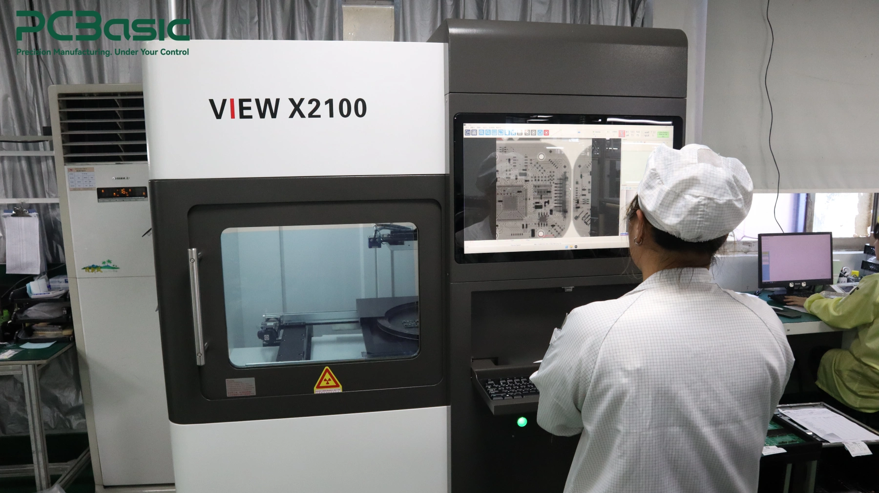
• X-ray inspection can check hidden solder joints, such as those under BGA components which cannot be seen from the outside.
Using different inspection methods gives manufacturers a better idea of the overall circuit board quality. At this point, your design may look ready. But looking ready is not enough. You need to prove that the process works 100%. And that proof comes during the important step between making a few boards and producing a thousand boards.
PCBasic combines different inspection methods according to the assembly requirements. Solder paste can be checked with SPI before placement, visible assembly defects can be inspected by AOI after reflow, and X-ray inspection can be used for hidden joints such as BGA and QFN packages. For projects that require electrical or functional verification, testing options can also include flying probe, ICT, and FCT.
Moving from a prototype to mass production should not happen all of a sudden. It is better to move step by step. Each stage helps you find different problems before they become costly at the end.
The first thing is that it is not always about making thousands of boards. It is about finding problems. A small prototype run can help you find footprint errors, tombstoning (when one end of a small component lifts from the PCB), soldering problems and parts that are difficult to test.
Fixing these things early is much cheaper. Changing a PCB pad during the prototype stage may only need a design update. Finding the same problem after production could lead to delays and extra costs.
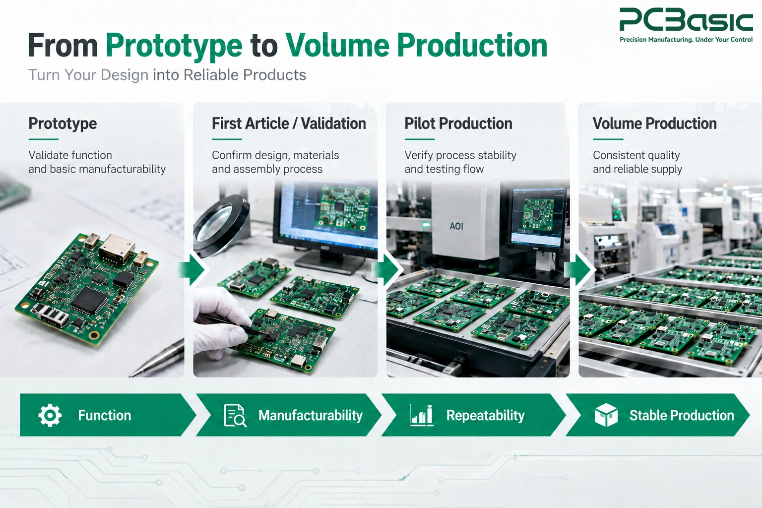
One working board does not tell you much. A pilot batch (means a small production stage before full-scale manufacturing process) gives you the real data.
Making a few hundred boards helps you measure the first-pass yield of your consumer electronics PCBA (printed circuit board assembly). First-Pass Yield means the percentage of boards that pass the required checks without rework, repair, or retesting.
It also helps you find repeated defects and see how the production line performs over time. And if one pilot batch performs well, the next batch should give similar results. That is when you can have greater confidence in the manufacturing process.
Inspection and testing are different.
• Inspection checks how the PCB was built. It looks for problems such as poor solder joints and other assembly issues.
• Testing checks whether the finished PCB actually works or not.
For example, a solder joint may look perfect during inspection but still fail when the device is working under a heavy load. That is why a proper production process needs both inspection and testing
A low price per circuit board may look really attractive. But it does not always mean you are saving money. What really matters is how many boards successfully pass the production.
See! A cheaper supplier may charge less per board but produce more defective units. A slightly more expensive supplier with better production quality and a higher first-pass yield (the percentage of boards that pass without rework) may actually cost less overall.
So, do not look only at the price of each PCB. Also consider the cost of repairs, delays, scrap, and failed units. The number that matters most is the cost per good board of your consumer electronics PCBA, because it better reflects the actual cost of production.

A good manufacturing partner should do more than place components and ship your PCBs. They should support you from the prototype stage through the mass production stage. This can include:
• Design and manufacturing reviews
• Prototype assembly
• Pilot production (small-scale production before the large-scale mass production)
• Inspection
• Functional testing
• Mass manufacturing
This is where a company can fit into the process by supporting consumer electronics PCB assembly from prototypes to larger production runs through one workflow. Reliable PCB assembly for consumer electronics depends on keeping the whole path (design, prototype, pilot, and mass) under one roof. A working PCB is not the finish line. It is the starting point.
|
Note: Production quality and defect rates can change depending on component selection and manufacturing conditions. Use real production data as a guide rather than expecting exactly the same results for every project. |
PCBasic supports consumer electronics PCB assembly from prototype and pilot builds through volume production. Its manufacturing capabilities cover SMT and through-hole assembly, SPI, AOI, X-ray inspection, and electrical and functional testing. For compact assemblies, PCBasic also supports fine-pitch components such as 01005/0201 packages and BGA/QFN devices, while MES-based production records help maintain traceability as projects move into larger production runs.
A fully working prototype does not mean your circuit board is ready for mass production. Turning that prototype into stable consumer electronics PCB assembly takes a few more checks. You also need to make sure that the design can be assembled properly and the process can control small changes during manufacturing. The best time to find a production problem is before producing in mass.
So, before starting a large production run make sure to test the manufacturing process behind your design. When you are ready to scale, PCBasic can support your project from DFM review and prototype assembly through inspection, testing, and volume production. Send your Gerber files and BOM to discuss your consumer electronics PCB assembly requirements.
Q1: Is a working PCB prototype ready for production?
No. A working prototype is not necessarily production-ready until the manufacturing process has also been properly validated before mass production.
Q2: Why can a PCB prototype fail in mass production?
A PCB prototype can fail in mass production due to small design and process problems. These problems can really become bigger when thousands of circuit boards are made.
Q3: How do you improve consumer electronics PCBA yield?
You can improve PCB assembly yield by using good designs, controlling solder paste, checking parts, testing boards and fixing process problems early.

Assembly Enquiry
Instant Quote
Phone contact

+86-755-27218592
In addition, we've prepared a Help Center. We recommend checking it before reaching out, as your question and its answer may already be clearly explained there.
Wechat Support

In addition, we've prepared a Help Center. We recommend checking it before reaching out, as your question and its answer may already be clearly explained there.
WhatsApp Support

In addition, we've prepared a Help Center. We recommend checking it before reaching out, as your question and its answer may already be clearly explained there.
