Global high-mix volume high-speed PCBA manufacturer
9:00 -18:00, Mon. - Fri. (GMT+8)
9:00 -12:00, Sat. (GMT+8)
(Except Chinese public holidays)
Global high-mix volume high-speed PCBA manufacturer
9:00 -18:00, Mon. - Fri. (GMT+8)
9:00 -12:00, Sat. (GMT+8)
(Except Chinese public holidays)
HomePage > Blog > Knowledge Base > What is ODB++? ODB++ vs. Gerber
Starting out with PCB design, the first few PCB layouts I exported for PCB fabrication were in Gerber files, and it never occurred to me to explore other options. Collaborating with experts in the electronics industry made me realize the need to explore other formats, such as ODB++, IPC-2581, and others.
This article highlights the importance of the ODB++ file format, its advantages over other formats, and when you should export your design using ODB++ files.

Open Database (ODB++) is a file format used mainly in the electronics industry by PCB designers and manufacturers to export PCB layout designs at the final stage of the design. It is primarily supported by popular software like the Altium Designer and Cadence Allegro. Even though ODB++ is not the most commonly used file format for exporting PCB design, there is no way a file that allows you to have every necessary data for PCB fabrication, assembly, and testing in one single ODB++ file package won’t make a name for itself in the electronics industry.
Valor Computerized Systems, a company that is now under the management of Siemens Digital Industries Software, introduced the ODB++ format in the early 1990s. Although it’s arguably not as popular as the Gerber format, it’s advantage of containing more necessary data for PCB manufacturing cannot be despised, and this has kept it relevant over the years and widely adopted by many, especially for a complex PCB design. Understanding what ODB++ is is essential for improving PCB design efficiency.

Advantages of ODB++
Would being an all-in-one file format that contains all the files needed for standard PCB manufacturing be a significant advantage for any format to leverage? Well, if you think it is, then you will find it more interesting to know that is not all there is to ODB++. Several other advantages unique to ODB++ have kept it relevant to date; some are listed below.
· The ODB++ format supports automation during the fabrication and assembly processes.
· The elimination of the need to generate multiple files and several file conversions in the ODB++ format makes it less prone to errors associated with conversion accuracy like some other formats.
· Pads and conductors, fiducials, and testing points are clearly differentiated by the ODB++.
· Design for Manufacturing (DFM) checks can be integrated into every layer, and this greatly reduces the chances of sending a design that cannot be fabricated to the manufacturer.
What Are the ODB++ File Extensions?
Earlier in the article, while defining the ODB++ format, it was mentioned that all the files necessary for the PCB fabrication and assembly, which include the layer data, netlists, and even the mechanical details, are embedded in just a single package. All the files contained in this zip package contain different files with their respective file extensions that can be seen when unpacked; they include:
· Matrix File (.matrix): The matrix file contains information about layer stack-up, which includes the copper layer, solder mask, silk screen, and others.
· Job File (.job): The information in this file includes the project’s name, dimensions, settings, and other instructions needed by the manufacturer.
· Layer Files (.comp, lyr): The component and layer extension contain each layer’s component placement, footprint, and attributes.
· Netlist File (.netlist): The electrical connection between different components on the PCB is referred to as the netlist. The netlist determines which pads or traces should be electrically connected.
· Padstack and Drill Files (.padstack, .drill, .drill_tools): The pad and drill data are saved in here. Saving this information in separate files makes it accessible independently and reduces the complexity of reading the already complex ODB++ file.
· Component Files (.components, .pins, .devices): The data stored in the file with these extensions include the position designator and rotation of components, pin location and connection for components, and details of each component necessary for both the design and assembly.
The following is a list of other extension files.
· Solder Mask and Paste File (.soldermask_top, .soldermask_bottom, .paste_top, .paste_bottom)
· Silkscreen Files (.silkscreen_top, .silkscreen_bottom)
· Fiducial Files (.fiducials)
· Test Point Files (.test_points)
· DFM (Design for Manufacturing) Files (.dfm)
· PCB Outline and Mechanical Files (.outline, .mechanical)
· Assembly Files (.assembly_top, .assembly_bottom)
· BOM (Bill of Materials) Files (.bom)
· STEP or 3D Model Files (.step)
· Assembly Drawings and Documentation (.drawings, .notes)

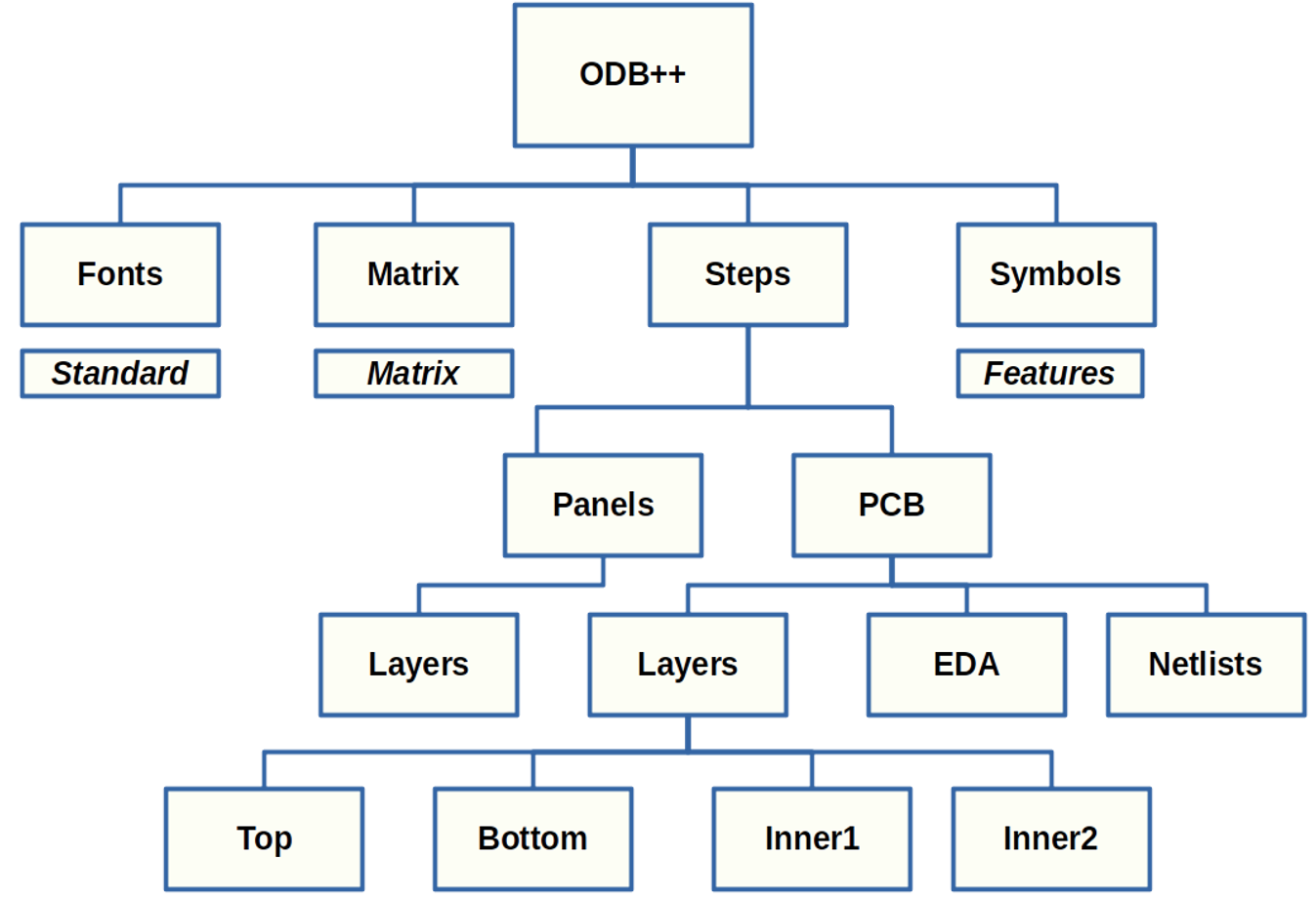
Even though an ODB++ file is exported and transmitted as a single zip file, its unpacking reveals several directories and files embedded within it. The size of the file when unpacked is mainly dependent on how complex the project is; below is a tree image of an unpacked directory of a typical ODB++ file.

The ODB++ format is wholesome; this implies it contains all the information required for all the faces of the fabrication process. For this reason, some individuals find the ODB++ complex, therefore making the need for a more streamlined version a necessity. The ODB++ family talks about the variant and extension of the ODB++ that is streamlined for a specific purpose. The ODB++ family includes:
· ODB++ Design: The ODB++ design focuses more on design-related information, such as component placements, Netlist, Layer Stack-up, and footprints.
· ODB++Manufacturing: This is a subset of ODB++ that focuses on the data needed for PCB manufacturing and assembly. In addition to the main data from ODB++, it contains the test point details, DFM rules, assembly instructions, and the solder mask and paste file.
· ODB++Process: This variant is not as popular as the other two on the list earlier. It focuses on process control and optimization and contains data for the machine set-up instruction, yield data, solder reflow speed, drill speed, and other process-specific information.
Several viewers were created specifically for viewing ODB++ format. For example, the Valor Universal Viewer (VUV) was created by the original creator of the ODB++ format Valor, which is now part of Siemen. Other viewers, such as the Valor ODB++ Viewer and ODB++ Viewers by Mentor Graphics (Siemens).
Meanwhile, there are several other viewers who were not primarily created to view the ODB++ format alone, but they support the ODB++ and other formats used for exporting PCB designs. They include CAM350, Gerbview, PentaLogix ViewMate Pro, and even the open-source KiCad has a plugin that supports viewing ODB++ files.
Although this article is not about the Gerber, but to successfully juxtapose the ODB++ and the Gerber file format the question “What is a Gerber file?” must be answered. Gerber file is another format that stores all the details in a PCB design layout in a format that can be interpreted by the Computer Aided Manufacturing (CAM) software.
The Gerber format is widely used and famous in the electronics industry. Before the introduction of the Gerber X2 format, the RSD-274-D and RS-274X format does not support multiple files in one package. Nevertheless, it’s still widely used and largely adopted by many PCB designers and manufacturers.
|
ODB++ |
Gerber Format |
|
It was later introduced in the 1990s by Valor. |
It was first introduced in the 1960s as RSD-274-D by Gerber System Corp. |
|
Mentor Graphics formally managed ODB++, but now Siemens EDA |
The Gerber format is currently managed by Umanco (it used to be Barco ETS). |
|
Embeds every PCB data from manufacturing to assembly to testing. |
Gerber format primarily focuses on data needed for manufacturing. |
|
It’s an all-in-one file; allow multiple layers in one file |
Most of the existing versions have individual files for each layer. |
|
Fewer conversion is required between design and manufacturing, reducing data loss or errors. |
Errors due to the conversion or missing data between separate files can occur. |
|
ODB++ is more complex to interpret manually due to the comprehensive data structure. |
It's easier to read manually since it's primarily a graphical format. |
|
It supports 3D component models and assembly data. |
The Gerber format does not support 3D models directly; separate assembly files are needed. |
|
DFM is fully supported across all layers |
Gerber format supports DFM check. |
|
It is supported by advanced CAD/CAM tools like Siemens EDA, Altium, and Zuken. |
It is universally supported by almost every PCB design and manufacturing tool. |
|
ODB++ is free to use, though managed as proprietary by Siemens EDA. |
The Gerber format is fully open and managed by Ucamco as an industry standard. |
In the end, mastering both ODB++ and Gerber format equips PCB designers and manufacturers with essential skills. Understanding the differences between ODB++ vs Gerber will help you decide when to use ODB++ files for your PCB projects. Familiarizing yourself with ODB++ file extensions ensures you'll be confident in choosing the right format for your next design.

Assembly Enquiry
Instant Quote
Phone contact

+86-755-27218592
In addition, we've prepared a Help Center. We recommend checking it before reaching out, as your question and its answer may already be clearly explained there.
Wechat Support

In addition, we've prepared a Help Center. We recommend checking it before reaching out, as your question and its answer may already be clearly explained there.
WhatsApp Support

In addition, we've prepared a Help Center. We recommend checking it before reaching out, as your question and its answer may already be clearly explained there.
