If you want to learn about a potentiometer
in all its aspects, in addition to knowing what a potentiometer is, you also
need to understand the types of potentiometers, its working principle, and the
difference between a potentiometer vs rheostat.
A potentiometer is a common
component in electronic devices, widely used in various circuit control
systems. Understanding what a potentiometer is used for is essential when
designing electronics.
In this
article, let’s discuss in detail what is a potentiometer, its working principle
and application, and its difference from a rheostat.

What is a Potentiometer?
First, what is a potentiometer? A potentiometer is a common
electronic component, often called a "pot", used to precisely control
voltage or current in a circuit. Understanding what a potentiometer is used for
helps us recognize its role in various devices.
The
core part of a potentiometer is a variable resistor, which is usually equipped
with three terminals: two fixed terminals and an adjustable sliding terminal
(also called a wiper). By rotating the control shaft of the potentiometer, people
can adjust the position of the wiper between the two fixed terminals, thus
flexibly changing the resistance value. This design makes the potentiometer
ideal for use in situations requiring precise adjustment.
The Potentiometer Diagram/ Symbol

In a
circuit diagram, the potentiometer’s symbol r is
usually represented as a resistor with an arrow. The potentiometer
symbol consists of two parts: a rectangular or jagged line representing
a fixed resistance element, and a diagonal arrow that intersects the resistance
element. The two terminals of the resistance element are connected with two
fixed terminals, representing the poles of the potentiometer, and the arrow
points to a certain position of the resistance element, indicating the sliding
contact of the potentiometer.
The Potentiometer Formula

The
operation of a potentiometer can be described using the voltage divider
formula. When the total resistance of the potentiometer is R, the wiper divides
this resistance into two parts: R ₁ and R ₂ . These two resistances add up to
the total resistance, so R ₁ + R ₂=R. The input voltage Vin is applied
across the two ends of the potentiometer, and the position of the wiper
determines the values of R ₁ and R ₂, which, in turn, affects the output
voltage Vout.
The
output voltage at the wiper, Vout , can be calculated using the following
voltage divider formula:
This
potentiometer formula can help us calculate the potential difference at any given
point along the resistive element.
Types of Potentiometers
With
the development of technology, electronic devices have higher and higher
requirements for components. Therefore, people have designed various types of
potentiometers according to different needs.
The
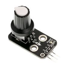
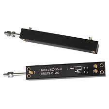
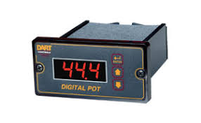
following are several common potentiometer types: rotary potentiometer,
linear potentiometer and digital potentiometer.
|
Type
of Potentiometer
|
Rotary
Potentiometer
|
Linear
Potentiometer
|
Digital
Potentiometer
|
|
Images
|
|
|
|
|
Adjustment
Method
|
Adjusts
resistance by rotating a shaft, typically between 270° to 300°, some can rotate 360° or multi-turn for
precise adjustments.
|
Adjusts
resistance by sliding the wiper along a straight path, changing the
resistance proportionally along the resistive element.
|
Adjusts
resistance through digital signals (via protocols like SPI or I²C) using a
microcontroller or digital circuit.
|
|
Structure
|
Three
terminals: two fixed terminals connected to the ends of the resistive
element, and a wiper that rotates along the element.
|
Three
terminals: two fixed terminals connected to the ends of the resistive
element, and a sliding wiper that moves along a linear path.
|
An
internal resistive network with electronically controlled switches. No moving
parts, controlled digitally.
|
|
Applications
|
Commonly
used in volume controls, brightness adjustments, and frequency tuning.
|
Used
in audio mixing consoles, electronic instruments, and lighting controls for
smooth linear adjustments.
|
Used
in applications requiring automated control such as audio adjustment,
automatic gain control, and remote-controlled systems.
|
|
Advantages
|
Simple
manual adjustment, easy to use for general applications.
|
Smooth,
linear adjustment; intuitive for manual control in devices requiring linear
changes.
|
No
mechanical wear, highly precise, programmable, and easy integration with
digital systems.
|
|
Disadvantages
|
Mechanical
wear can occur over time with repeated use.
|
Limited
travel distance and potential wear from frequent use.
|
Limited
resolution, requires external power and control signals, more complex to
integrate.
|
How does a Potentiometer Work?
How
does a potentiometer work? It’s very easy. It adjusts the output voltage or
resistance value by changing the position of the sliding contact on the
resistance element.
When
the slide moves along the resistance element, the potentiometer changes the
resistance of the two parts of the circuit, thus changing the output voltage.
By adjusting the position of the slide, the resistance ratio of the two parts
can be adjusted, which directly affects the output voltage.
As we
can see from the potentiometer diagram above, the movement of the slide splits
the total resistance into two parts, enabling it to function as a voltage
divider or variable resistor.
For
example, in the volume control knob, rotating the potentiometer can adjust the
resistance to change the volume. In a tuning circuit, a potentiometer adjusts
the tuning frequency of a radio receiver by changing the voltage in certain
sections.
How to Wire a
Potentiometer

Learning
how to wire a potentiometer is an important step in the proper use of a
potentiometer in a circuit. By referring to the detailed steps and explanations
below, you can easily master potentiometer wiring.
Step 1:
Identify the Terminals
A potentiometer
has three metal terminals, which are in
different positions and functions.
•
Terminal 1:
This
is the first fixed terminal, connected to one end of the resistive track.
Regardless
of how you turn the knob, the resistance value between Terminal 1 and the
opposite end of the track remains constant.
•
Terminal 2 (Wiper):
This
is the wiper, the core part of the potentiometer.
When
you rotate the potentiometer’s knob, the wiper moves along the resistive track,
changing the resistance value.
This
terminal is typically used for output voltage or current control.
•
Terminal 3:
This
is the second fixed terminal, located at the other end of the resistive track.
Like
Terminal 1, the resistance value between Terminal 3 and the opposite end of the
track remains constant.
Step 2:
Choosing the Correct Wiring Method
The
wiring method depends on the application of the potentiometer. Here are two
common wiring methods:
1.
Voltage Control Wiring
This
method is used for adjusting output voltage, commonly found in volume controls,
light dimmers, etc. Follow these steps:
•
Connect Terminal 1 and Terminal
3 to the positive and negative terminals of the power supply (or to the
power source and ground).
•
Connect Terminal 2 (the wiper)
as the output. The output voltage will vary as you turn the knob.
•
When the knob is turned fully to one
side, the output voltage will be close to the power supply voltage. When turned
to the opposite side, the output voltage will approach zero.
2.
Variable Resistance Wiring
This
method is used to control the flow of current, such as adjusting fan speed or
dimming lights. Follow these steps:
•
Connect Terminal 2 (the wiper)
to one end of your circuit.
•
Connect either Terminal 1 or Terminal
3 to the other end of the circuit.
•
As you turn the knob, the resistance
value will change, controlling the current flow accordingly.
Step 3:
Testing the Wiring for Accuracy
Before
integrating the potentiometer into your circuit, be sure to verify the wiring
using a multimeter:
1.
Check the Fixed Terminals' Resistance: Use a multimeter to measure the resistance between Terminal
1 and Terminal 3. This value should match the potentiometer’s
maximum rated resistance (e.g., 10kΩ).
2.
Test the Wiper's Changing Resistance: Measure the resistance between Terminal 2 and Terminal
1 (or Terminal 3). As you rotate the knob, this resistance should
vary between 0Ω and the maximum resistance value.
Step 4:
Refer to a Potentiometer Diagram
For
clearer understanding, referring to a clear potentiometer diagram can greatly
improve your wiring accuracy. The diagram will label each terminal and show the
correct connection method.
By
following these detailed steps, you can easily learn how to wire a
potentiometer correctly, ensuring your circuit functions properly and achieves
the desired adjustment results.
Potentiometer vs Rheostat
What is Rheostat?

From
the above, we learned that the potentiometer has three terminals and can also
be used as a voltage divider. Unlike a potentiometer, a rheostat is a two-end
device that adjusts the current in the circuit by changing the resistance
value.
Difference between a Potentiometer and a Rheostat
A potentiometer
and a rheostat are mainly different in use. The potentiometer is mainly used to
control voltage, while the rheostat is used to control current.
At the
same time, the potentiometer can also be used as a variable voltage divider,
and the rheostat can be used as a resistor to adjust the current flow.
Structurally,
the slide of a potentiometer divides the resistance element into two parts,
while in a rheostat, the slide controls the circuit only by adjusting the total
resistance.
Conclusion
All in
all, a potentiometer is a crucial component in
electronic circuits.
It offers precise control over voltage by adjusting resistance. Its basic
working principle, potentiometer symbol, and
formula show us how it can divide voltage or act as a variable resistor.
With
various types of potentiometers available,
potentiometers are widely used in applications such as audio control, light
dimming, and tuning circuits. When comparing potentiometers vs rheostats, the
primary difference is that potentiometers control voltage, while rheostats
control current. Understanding these differences is essential for selecting the
right component for your circuit.
Understanding
what a potentiometer is, what a potentiometer does, how a potentiometer
works, and the
differences between potentiometer vs rheostat is essential for selecting the
right component for your potentiometer circuit.