Global high-mix volume high-speed PCBA manufacturer
9:00 -18:00, Mon. - Fri. (GMT+8)
9:00 -12:00, Sat. (GMT+8)
(Except Chinese public holidays)
Global high-mix volume high-speed PCBA manufacturer
9:00 -18:00, Mon. - Fri. (GMT+8)
9:00 -12:00, Sat. (GMT+8)
(Except Chinese public holidays)
HomePage > Blog > Knowledge Base > What Is SMT Assembly?
Surface Mount Technology (SMT) is a method used to produce electronic circuits by mounting SMT components directly onto the surface of printed circuit boards (PCBs). This SMT assembly process has revolutionized the electronics manufacturing industry, offering numerous advantages over traditional through-hole technology.
In this blog, we will dive deep into SMT assembly, exploring what is SMT assembly, the steps involved in the SMT process, and its advantages and disadvantages.

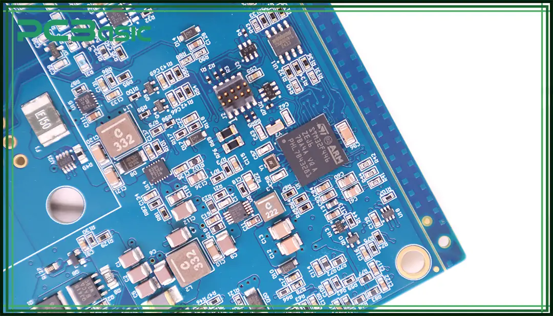
SMT assembly, or Surface Mount Technology assembly, is a method in which SMT components are mounted directly onto the surface of a PCB. These components are known as Surface Mount Devices (SMDs), and they differ from traditional components that require leads to be inserted into holes drilled into the PCB.
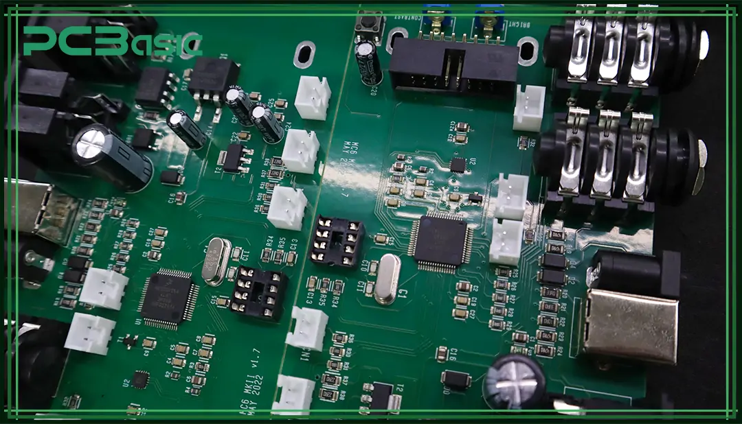
Surface Mount Devices (SMDs) are electronic components designed specifically for SMT assembly. Unlike traditional through-hole components, which have long leads that need to be inserted into holes on a PCB, SMD components are smaller and have short leads or no leads at all. They are placed directly on the surface of the PCB and soldered in place.
SMD components come in various types, including resistors, capacitors, diodes, transistors, and integrated circuits. Their compact size allows for higher component density on PCBs, which is essential for modern electronics that demand smaller and more powerful devices.

The SMT assembly process involves several key steps that must be carefully executed to ensure high-quality SMT PCB assembly. Below is an overview of the typical steps involved in SMT assembly:
1. Solder Paste Application
The first step in the SMT assembly process is applying solder paste to the PCB. Solder paste is a mixture of tiny solder balls and flux, which helps the solder bond to the SMT components during reflow soldering. The solder paste is applied to specific areas of the PCB where SMD components will be placed using a stencil.
2. Component Placement
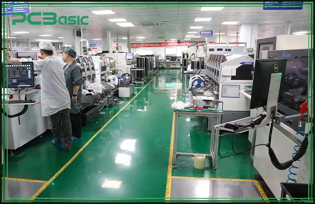
Once the solder paste has been applied, SMT components are placed onto the PCB using automated machines called pick-and-place machines. These machines are programmed to accurately place each SMT component onto its designated position on the board. The use of automation ensures precision and speed in placing even the smallest SMD components.
3. Reflow Soldering
After all SMT components have been placed on the PCB, the board undergoes reflow soldering. In this process, the PCB is passed through an oven where it is heated to a temperature that melts the solder paste. As the solder cools down, it solidifies and creates strong electrical connections between the SMD components and the PCB.
4. Inspection
Once reflow soldering is complete, it’s crucial to inspect the SMT PCB assembly for any defects or misalignments. Automated Optical Inspection (AOI) systems are commonly used for this purpose. AOI systems use cameras to capture images of the assembled board and compare them with reference images to detect any issues such as missing SMT components or poor solder joints.
5. Testing
After inspection, functional testing is performed to ensure that the assembled board works as intended. This step may involve electrical tests such as In-Circuit Testing (ICT) or functional testing where power is applied to check if the circuit operates correctly.
6. Rework (if necessary)
If any defects or issues are identified during inspection or testing, rework may be necessary. Rework involves manually correcting any problems by replacing faulty SMT components or repairing poor solder joints.

SMT assembly offers several advantages over through-hole technology, making it the preferred choice for modern electronics manufacturing:
1. Higher Component Density
One of the most significant advantages of SMT assembly is its ability to accommodate a higher component density on PCBs. Since SMD components are smaller than traditional through-hole components and do not require holes to be drilled into the board, more components can be placed on both sides of a PCB. This allows manufacturers to create smaller and more compact devices without sacrificing functionality.
2. Faster Assembly Process
The use of automated pick-and-place machines in the SMT process significantly speeds up production compared to manual insertion of through-hole components. Additionally, reflow soldering allows multiple SMD components to be soldered simultaneously, further reducing assembly time.
3. Cost Efficiency
SMT PCB assembly can lead to cost savings in several ways:
- Reduced labor costs due to automation.
- Lower material costs since fewer holes need to be drilled into PCBs.
- Smaller PCBs can be used due to higher component density.
These factors contribute to lower overall production costs for manufacturers.
4. Improved Performance
SMD components typically have better electrical performance than their through-hole counterparts due to shorter lead lengths, which reduce parasitic inductance and capacitance. This results in improved signal integrity and faster circuit operation—important factors in high-frequency applications like telecommunications and computing.
5. Flexibility in Design
SMT PCB assembly allows for greater flexibility in PCB design since SMT components can be mounted on both sides of a board if needed. This flexibility enables designers to create more complex circuits without increasing board size.
While SMT Assembly offers many benefits, it also comes with some limitations:
1. Difficulties with Large Components
Although SMT PCB assembly works well with small SMD components like resistors and capacitors, it may not be suitable for larger or heavier components that require stronger mechanical support—such as transformers or large connectors—which are better suited for through-hole mounting.
2. Higher Initial Setup Costs
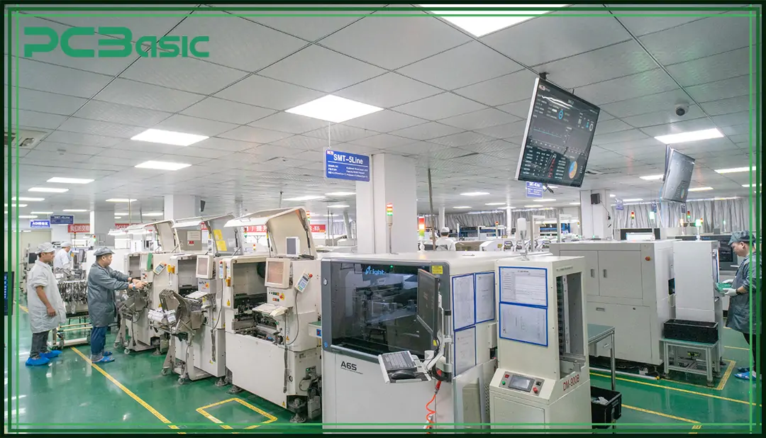
Setting up an SMT PCB assembly production line requires significant investment in specialized equipment such as pick-and-place machines and reflow ovens. While these costs can be offset by higher production volumes over time, they may pose a barrier for small-scale manufacturers or prototyping purposes.
3. Challenges with Prototyping and Repair
Because SMD components are smaller than traditional components and often lack visible leads, they can be more challenging to handle during prototyping or repair processes compared to through-hole components that are easier to manipulate manually.

When it comes to reliable and cost-effective PCB assembly services, PCBasic offers comprehensive SMT PCB assembly solutions tailored to your needs. Whether you require precision, flexibility, or rapid production, its advanced SMT process ensures optimal results.
PCBasic is a trusted PCB assembly services provider specializing in a wide range of solutions to meet the diverse needs of industries worldwide. With years of experience and a dedicated team of experts, PCBasic has built a reputation for delivering high-quality SMT PCB assembly solutions with fast turnaround times and competitive pricing.
Its comprehensive services include:
• Custom Design Support: Our skilled engineers collaborate with clients to optimize PCB designs for manufacturability and performance.
• Prototyping and Small-Batch Production: Ideal for testing new designs or fulfilling limited production needs with precision.
• High-Volume Manufacturing: Equipped with advanced automated equipment, we excel in mass production to meet bulk orders efficiently.
• Quality Assurance: Rigorous inspection procedures such as Automated Optical Inspection (AOI) and X-ray testing ensure all SMT components are properly placed and soldered.
• Global Supply Chain Support: PCBasic leverages a vast network of suppliers to source reliable SMD components and maintain stable production lines.
With our commitment to excellence and customer satisfaction, PCBasic is the perfect partner for your SMT PCB assembly requirements.
Understanding what SMT assembly is, what SMDs are, and the key benefits of SMT components can help you make informed choices for your electronics manufacturing projects.
At PCBasic, it specializes in delivering high-quality PCB assembly services, utilizing advanced SMT assembly techniques to meet your production goals efficiently. Contact PCBasic today to learn more about our affordable and reliable SMT PCB assembly solutions.

Assembly Enquiry
Instant Quote
Phone contact

+86-755-27218592
In addition, we've prepared a Help Center. We recommend checking it before reaching out, as your question and its answer may already be clearly explained there.
Wechat Support

In addition, we've prepared a Help Center. We recommend checking it before reaching out, as your question and its answer may already be clearly explained there.
WhatsApp Support

In addition, we've prepared a Help Center. We recommend checking it before reaching out, as your question and its answer may already be clearly explained there.
