The SCR, or silicon-controlled rectifier, is an electronic
component that is used in different electronic circuits and devices as
switches. It is structured with 3 terminals that help to control the magnitude
and direction of current flowing in the circuit. Its common uses are in
industries for different circuits, such as lighting circuit controls, motor
speed control, and high-power transmission lines.
Silicon is commonly used for the creation of different
semiconductor components, and SCR is also made with this material. It is mainly
used for rectifier circuits, which means AC to DC conversion, so it is known as
a controlled rectifier. In this tutorial, we will discuss its working,
features, applications, and other features. Let's get started with.
What is a
silicon control rectifier?
The SCR is a semiconductor device that is used as a switch to
control AC or DC flow in circuits. It has a 4-layer structure that is
configured as a PNPN combination. In this PNPN, there are 3 PN layers. Its
design is such that when no power supply is connected to its terminal, it works
as an open switch. If the positive lead of the power source is connected with
the gate terminal of the SCR, as a result of a small current, the SCR starts
operating and the current passes through it. The current continues to flow
until the power is disconnected. SCR was first made by General
Electric (GE) in
1957. At that time, it was known as an SCR or silicon-controlled rectifier; it
was also known as a thyristor.
What does SCR stand for?
SCR stands for silicon-controlled rectifiers, and it is a
four-layer semiconductor material-configured device.
Different types and packages of SCRs
Discrete Plastic:
It is a very commonly used type of SCR and has 3 pinouts that
are configured with plastic-coated semiconductor material. This SCR has planer
designs and has a lower cost than other types. It is used for 25-volt to
1000-volt applications. It has space for connection, so larger components of
circuits.
Plastic Module:
It comes with more than one device, has a current range of
about 100 ampers, and has the same features as a discrete plastic type. It is
connected to a printed circuit board by bolting the heatsink.
Press Pack:
This type of SCR is used for high-current projects such as
200 Amperes of current or higher and a voltage value of 1200 volts or higher.
Its inner structure is converted with ceramic casing and has separation or
insulation between the cathode and anode.
Stud Base:
Stud-base SCRs come with screwed bases and
supports five to 150 amperes of current through the use of a complete voltage
range. They have low
thermal resistance and can efficiently dissipate heat. They are mechanically
attached to the heatsink, making them more difficult to
remove
Flat Base:
It comes with a separation from the heatsink with the use of
insulation, and its features are like stud-base SCR. Its current range is 10 to
400A.
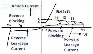
Characteristics of SCRs
For finding the VI characteristics of SCR, 3 operating
regions are used: forward block, forward conduction region, and reverse block
region.
There is a small leakage current flowing in the reverse direction for reverse blocking mode that is seen on the negative
side of the graph.
For forward blocking mode, the anode is positive supply
connected and the cathode is negative. As a result, a small leakage current
passes through the SCR in a positive direction, and the graph is in a positive direction.
After reaching a certain voltage level, which is known as
breakdown voltage, the SCR is in conductive mode with high current flow.
The gate current in the graph is devoted to I1, I2, and I3,
and for high gate current, high conduction will be of SCR.
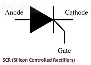
What is the
SCR symbol?
The symbolic representation of Silicon Rectifiers is like a
diode. That means it has a diode and cathode-like diode with additional
terminal gates. SCR allows current to flow in one direction and stops in the
reverse direction. Its 3 terminals are anode, cathode, and gate, which are
denoted as A, K, and G, respectively. Gate terminals are used as control points
and are on or off the SCR.
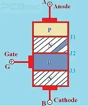
What's the
construction of the SCR?
As mentioned above, we discussed that SCR has 4 layers that
can be in combination with PNPN or NPNP. In these four layers, 3 PN junctions
are denoted as J1, J2, and J3. Its anode is a positive terminal, that is the P
layer, and the cathode is a negative electrode, that is the N layer. Gates are
used for controlling the SCR.
Its P and N layers with 3 electrodes are highly doped, and
the middle P and N layers are less doped, and the gate is configured with a P
layer. An SCR comes with 3 types of construction: Mesa, Planar, and Press Pack
How does an
SCR work?
SCR working is like a diode, which means it allows current to
flow in the forward direction and block in the reverse direction. It has
features for handling high voltages.
Its gate controls the flow of positive forward current in the
anode. The application of a short pulse at the gate allows SCR to work between
the anode and the cathode. As a result, anode current flows become zero when
SCR is off. For again, the condition of the voltage gate gets another pulse.
There are 3 main working modes of operation of SCR.
Forward Blocking Mode
●
Positive voltage is connected to the anode and negative at
the cathode. In forward blocking mode, J1 and J3 are forward-biased, and
J2 is reverse-biased. This prevents current from flowing until the gate
triggers conduction.
Forward Conduction Mode
●
In this mode, SCR will be on state and operate. There are 2
methods for the conduction of SCR. The first one is higher forward-biased
voltage as compared to breakdown or providing a positive supply at the gate
terminal.
Reverse Blocking Mode
●
The positive terminal of the battery has a cathode and the
negative with the anode of the SCR. When voltage is provided, Junctions J1 and
J3 are working as reversed biased and J2 is forward biased.
5. Applications
of controlled rectifiers
●
It is used as a rectifier and switched from AC to DC
conversion.
●
It is used for high-power handling and current circuits and
easily turns off with low voltage.
●
It is used in power supply circuits and motor speed
controllers.
●
It is used for voltage regulator circuits to provide constant
voltage for the device working.
The SCR is now an important semiconductor device that is used
for different electronic projects and circuits. It is the main component for
power-handling circuits and is mostly used for the electrical system. It is
also used for managing components working from overvoltages and is mostly used
in rectifiers. It needed voltage work, and its 3 modes make it a complicated
device for working in circuits. SCR is mostly used as compared to members of
thyristor groups such as DIAC or TRIAC. Its high current handling features help
it be used for applications where high current is involved, like welding
devices and large inverters.