Global high-mix volume high-speed PCBA manufacturer
9:00 -18:00, Mon. - Fri. (GMT+8)
9:00 -12:00, Sat. (GMT+8)
(Except Chinese public holidays)
Global high-mix volume high-speed PCBA manufacturer
9:00 -18:00, Mon. - Fri. (GMT+8)
9:00 -12:00, Sat. (GMT+8)
(Except Chinese public holidays)
HomePage > Blog > Knowledge Base > Understanding Metal Core PCBs (MCPCBs)
As technology evolves, electronic devices are becoming more and more powerful, and with that comes different problems, including overheating. Metal Core Printed Circuit Boards (PCBs), also known as metal core PCBs or MCPCBs, are becoming increasingly desirable components of electronic devices today, especially those that require effective thermal management. These metal core circuit boards are ideal for thermal control in compact, high-power systems.
We talk about the benefits of metal core PCBs in electronic devices and explore high-power electronic components that can help you maximize the potential of any electronic project. Whether you're working with an aluminum PCB, a copper core PCB, or a hybrid metal core board, choosing the right metal core PCB manufacturer or MCPCB manufacturer is crucial.
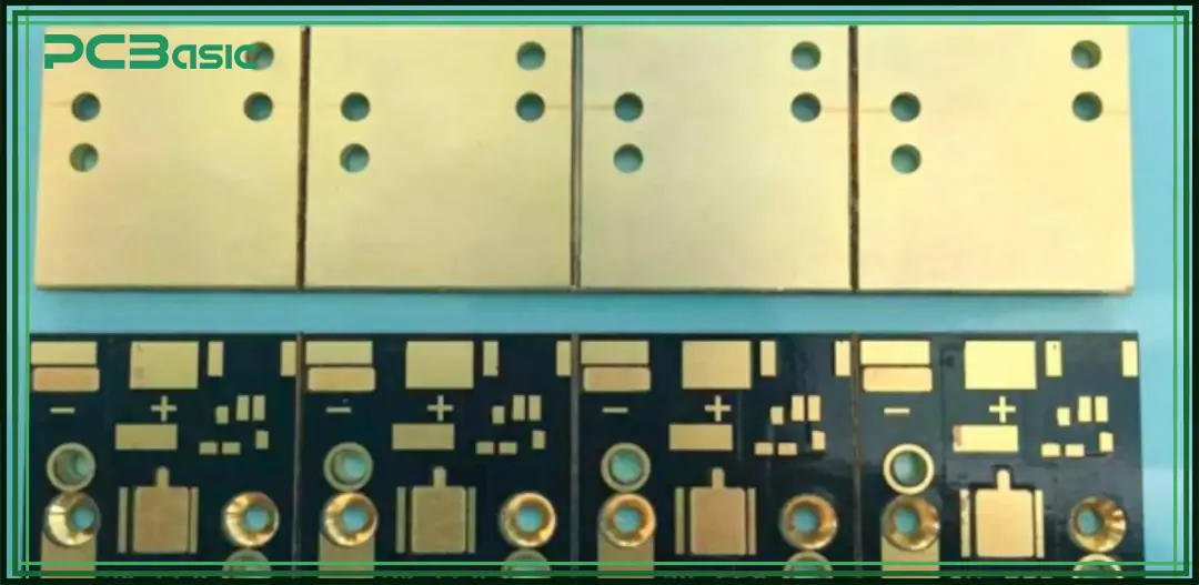
There are several names for this sort of circuit board, including Insulated Metal Substrate PCB, aluminum clad, aluminum base, and metallic PCB. All of these terms refer to various types of metal core printed circuit boards, or metal core PCBs, which mostly have identical benefits and characteristics.
Metal core PCB circuit boards, as the name suggests, feature a metal base core near the heat dissipator portion of the board. The PCB metal core can be placed in the middle of the surface underneath the board or on the outside rear. This design is consistent across different metal circuit board variants, including both aluminum PCBs and copper core PCBs.
Metal has high thermal conductivity, which is crucial to a circuit board. The metal core plays a significant role in cooling systems by directing heat away from the main electronics of the PCB to essential components such as the metal heatsink backing or the core.
Depending on the use of the target electronics, metal core PCB circuit boards can be single or double-sided. However, multilayer metal core PCBs are not widely used due to the complexity of the manufacturing process.
Typical circuit boards feature FR4 or CEM3, while metal core PCB boards feature metallic cores instead. Besides heat dissipation, metal core PCB boards offer mechanical stability and maintain electric isolation between circuit layers and components.
Metal core PCBs can feature aluminum, copper, or metal cores. In some cases, metal cores can be mixtures of different special alloys. For example, brass or steel can be used, but it is not recommended because of their hardness, making it difficult to break down the circuit board into many pieces.
Aluminium core PCBs are the most common type of metal-core PCB circuit boards, which conduct heat generated by the heat-intensive components away from the board more efficiently. This facilitates a more even distribution of heat dissipation throughout the PCB.
Some PCBs also feature copper cores, which improve thermal conductivity and help lower the working temperatures within components.
Although copper is an excellent choice for electronic devices prone to overheating, it is an expensive option compared to aluminum. Metal core PCB manufacturers mainly use copper core in the following situations:
● Single Side Single Layer: A PCB equipped with a single layer of a pedestal made of copper for cooling purposes.
● Copper-Filled Laser Thermal Via Matrix: In metal-based circuit boards, copper-filled vias are laser-drilled, forming a network that improves heat conduction compared to normal vias.
● Double-Sided Pedestal: In a double-sided PCB, there is a copper-based pedestal on the two sides for quicker heat dissipation.
The structure of a typical metal core PCB includes a solder mask layer, a dielectric layer, and a metal core at the bottom.
The first layer is the solder mask layer, followed by a circuit and copper layer. These layers lie on a dielectric in between, which is a metal core layer. The upper copper film layer consists of a thin copper film with circuit traces. The thickness of this layer ranges from 1oz to 4oz (ounces per square foot).
The innermost layer acts as the dielectric layer. It isolates the metal core from the copper film while facilitating heat transfer between the layers.
The metal core is the lowest layer. The metal used is usually aluminum, and its thickness ranges from 1mm to 3.2mm. The metal core is a heat spreader, absorbing heat from the heat-generating components and dissipating it. It is the thickest layer found in a PCB, giving the board rigidness and making sure the PCB stays flat.
The core makes the circuit board thick enough to be compatible with all standard board mounting hardware, and the exposed metal part of the board is not covered with a surface finish or solder mask.
The metallic core of the metal core PCB has high thermal conductivity, typically between 1W/mK and 9W/mK. The high thermal conductivity combined with a thin insulation layer of about 100µm enables the board to transfer heat quickly.
Metal core PCBs are widely used in electronic devices because of their excellent thermal performance, better capacitive coupling, and high electromagnetic shielding. Let's explore the advantages of metal core PCBs in more detail:
Metal is known for its high thermal conductivity, making MCPCBs ideal for devices facing heating challenges. The components facilitate heat transfer across the appliance, reducing localized heating problems. The heat conduction capabilities make metal core PCBs ideal for high-power-level circuits.
A heat production experiment was conducted on 1W LED fixtures mounted with either a metal core PCB or an FR-4 PCB. Overheating had little to no impact on the metal core PCB, while the FR-4 PCB overheated to 37°C.
LED technology manufacturers, especially high-power LED lighting manufacturers, have highlighted the issue of overheating in recent years.
High-power electronic devices are prone to malfunctioning without an efficient heat-dissipating mechanism. Metal core PCBs address this issue by evenly distributing heat across the device via the metal core, thereby minimizing damage from heating.
Aluminium is a lightweight material that provides strength to the printed circuit board without necessarily adding weight to the entire electronic device, thereby making the PCB ideal for high-power LED lighting.
 About PCBasic
Time is money in your projects – and PCBasic gets it. PCBasic is a PCB assembly company that delivers fast, flawless results every time. Our comprehensive PCB assembly services include expert engineering support at every step, ensuring top quality in every board. As a leading PCB assembly manufacturer, we provide a one-stop solution that streamlines your supply chain. Partner with our advanced PCB prototype factory for quick turnarounds and superior results you can trust.
Metal-core PCBs boast relatively higher dimensional stability than PCBs made from traditional materials like FR-4, especially under fluctuating environmental conditions.
For instance, a metal PCB material that was exposed to heating processes ranging from 30°C up to 150°C showed a dimension change of between 2.5% and 3.5% compared to the conventional which expanded to about 4%.
However, metal core PCB such as aluminum or copper, due to their superior thermal stability, can effectively resist this thermal stress and maintain consistency across different temperatures. This stability lowers the risk of circuit board warping at high temperatures.
Traditional PCBs are primarily made of delicate materials like ceramic and fiberglass, which are weak and destructible. On the other hand, metal core PCB circuit boards are stronger, thanks to the metal core.
Metal circuit boards reduce the risk of breaking or damage during the circuit board manufacturing and assembly processes. They extend the lifespan of the appliance.
The quality ensures that the printed circuit board can withstand mechanical pressure during manufacturing. The durability and strength of the electronic ensure that it will not break when stressed mechanically.
Metal core PCB circuit board variants are more lightweight and, hence, cost-effective.
Aluminium is easier to refine, which makes it a cost-effective choice for circuit board substrates, reducing manufacturing costs for aluminum-based boards.
Hence, aluminum circuit boards provide a budget-friendly alternative to bulkier and pricier options.
Aluminium is a recyclable material, which makes metal core PCBs more environmentally friendly and cost-effective. It is one of the most recycled materials on earth. It can be recycled repeatedly without depreciation of quality.
Metal core PCBs are categorized into different types based on the different positions of the metal core in MCPCBs. Some of the different types of metal core PCBs include:
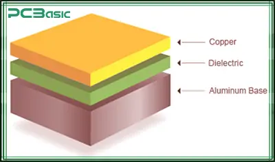
As the name suggests, a single-layer MCPCB is built from a single copper conductive layer. This is followed by a metal base plate which makes the circuit board rigid.
The thermal conductive circuit layer insulates the circuit board, making it suitable for simpler applications where overheating is not a concern.
The core is usually made from aluminum. The basic structure of a single-layer circuit board consists of a metal core (usually aluminum) and a dielectric or insulation layer. This structure is most suitable for audio devices, sensors, packaging equipment, and automotive relays.
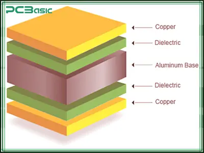
A double-sided PCB consists of two layers, with the metal core sandwiched between these copper layers, interconnected using Plated Through Holes (PTH) that connect the copper layers.
The metal-core PCB manufacturers can use the double side of the circuit board for mounting the SMT and THT components. Double-sided MCPCBs are utilized in complex circuit designs with trace layers on both sides of the metal core.
Laminating the two copper layers to the copper core necessitates both material and skill. Some metal-core PCB suppliers provide pre-laminated sheets for the metal covering, streamlining the process.
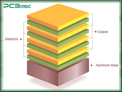
As the name implies, a multilayer metal circuit board houses more than two conductive layers. The metal base is situated at the bottom, enabling manufacturers to mount their components on just one side of the board.
In multilayer PCBs, the metal core is placed between the other layers, with an equal number of layers below and above the core. For instance, a metallic PCB with 12 layers would have exactly 6 layers above and below its metal core.
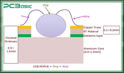
A chip-on-board MCPCB is used when thermoelectric separation is necessary. They save space while boasting performance.
In standard metallic PCBs, there is a dielectric layer between the copper traces and the metal core, which limits thermal conductivity due to the insulating properties of the dielectric layer.
On the other hand, COB MCPCBs feature a chip on the metal core, which facilitates heat dissipation. This setup produces an electrical interconnection between the chip and the circuit board traces.
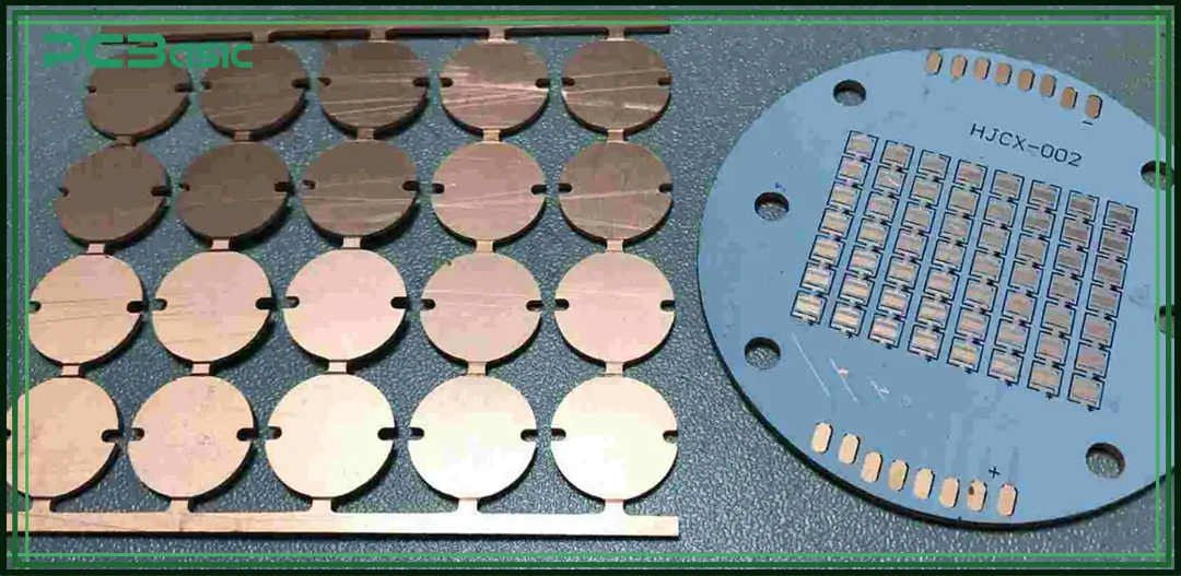
Metal core PCBs are manufactured the same way as traditional PCBs except for a few different steps due to the addition of a metal core.
The process starts with selecting an appropriate material for the MCPCB, depending on where it will be used. The application of a specific PCB determines what material is best for the core, insulation layer, and copper foil.
Material selection is usually based on the level of thermal conductivity, dielectric constant, and mechanical properties required.
Before metal placement and routing, Metal core manufacturers drill the metal core with holes using computer-controlled drilling machines, which maximizes consistency and accuracy. The drilling machine automatically selects the correct drill and loads the drill head into the machine.
Although drill machines boast high-speed drilling, it is a time-consuming process because each hole must be drilled one by one.
The metal core is coated with a thin layer of copper. This is done via electroplating, a process that involves electrolytic plating of metal.
The copper layers are covered with a layer of optically active organic film called photoresist. After exposure to UV light, the pattern of the outer film is applied to the board surface. Exposing the structure to UV light via a photomask results in a copper trace pattern.
Areas where photoresist wasn't applied are etched to remove excess copper, leaving the copper trace pattern intact and eliminating excess copper on the board.
A high-temperature polymer layer, also called an insulation layer, is laminated onto the metal core on both sides. This step ensures that the copper traces are covered with the insulation layer.
A solder mask layer is applied to both sides of the metal PCB. this is a protective photo imageable lacquer layer that protects the board from damage due to oxidation and environmental exposure. Hence, the board remains safe from dust and other components.
Metal core PCB manufacturers leave openings in the solder mask layer to facilitate component placement and soldering.
Routing is done at the end of the production process to create the contour of the circuit board. This is typically done using a computer-controlled CNC machine or milling tool, which drills internal cut-outs or slots. The machine is programmed to follow a pre-defined path in the original tool file.
The dust produced during milling is collected by the brush located near the milling head. It uses a vacuum-like system to suck in the dust.
The copper layers are coated with another layer of metallic or organic material intended to protect the exposed copper layers from oxidation and environmental damage.
At the last manufacturing stage, v-scoring or v-grooving occurs by cutting a V-shape on both sides of the circuit board. A minimum amount of material remains, allowing metal core PCB manufacturers to separate the PCB from the production panel.
Just like any electric component, a circuit board must be tested to ensure quality and proper functioning.
Metal core PCB manufacturers perform electrical tests on circuit boards using flying probe testers for complex circuit boards. Additionally, they may utilize universal grid testers to test large batches of circuit boards.
This test checks whether the electrical safety of metal core PCBs meets the specified characteristics and insulation performance standards. It involves measuring the insulation resistance and breakdown voltage of circuit boards.
The reliability test may also detect defects in the circuit board, including pinholes on the insulator, broken or damaged insulator, or low electrical clearance between components.
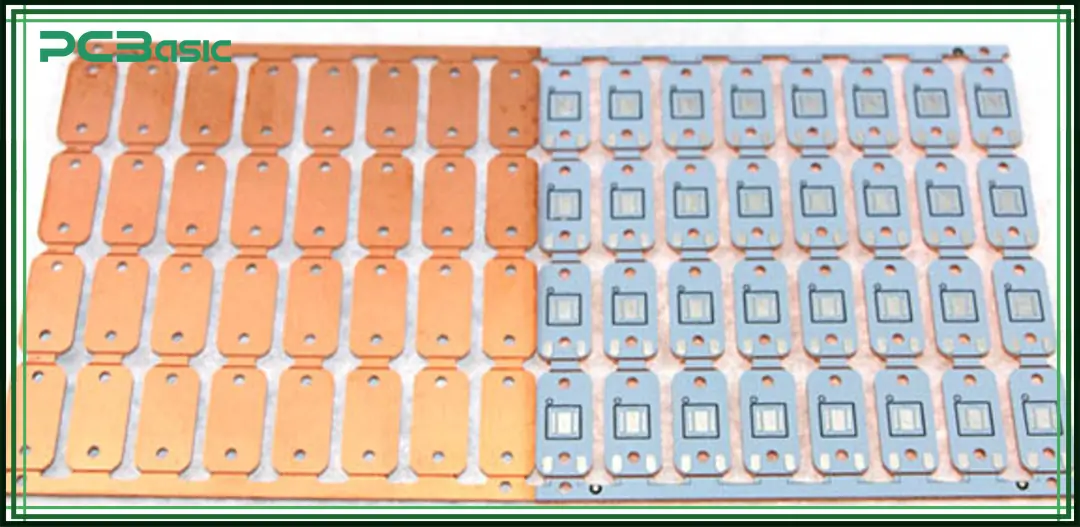
Metal circuit board manufacturing involves evaluating several factors to ensure optimal performance and reliability. This includes:
The higher the thermal conductivity of the core material, the faster it dissipates heat away from the heat-generating component in the electronic appliance.
As a result, the core material and its thickness are dependent on an appliance's power requirements and the rate at which heat needs to be removed from the appliance.
The metal core PCB’s performance also depends on the type of insulation material, which is the dielectric constant in MCPCB manufacturing. The insulation material, placed between the core and the copper layers, has a dielectric constant.
The dielectric constant affects the conductance of a metallic board. A higher dielectric constant increases the capacitance and signal transmission. A low dielectric constant lowers the capacitance of a metallic circuit board and signal transmission.
Depending on the signal transmission needed for a specific application, the metal core PCB manufacturer selects the insulating material according to its dielectric constant.
The current-carrying capacity and the voltage requirement of a specific application also determine the size of the board, and the spacing is left between two traces. Therefore, the board's spacing and width are likely to affect efficiency.
The solder mask and silkscreen protect the copper layers of the board. They also help identify the board and the components through coloration and labeling. The color of the mask and silkscreen is dependent on an application's need.
MCPCBs are subjected to shock, vibrations, and significant temperature variations. Therefore, the board must be stable enough to withstand mechanical stress. The stability of the board is dependent on the type of material used, the thickness of the core, and the connection made.
Considering these factors, it is critical to work with an experienced MCPCB manufacturer who will guarantee that the circuit board delivers optimal performance and meets the specific requirements of the application.
It is critical to consider the difference between FR-4 circuit boards and metal PCBs to understand the applications of metallic circuit boards.
Various electronic appliances need a great deal of energy to work. It also generates a significant amount of heat, which can sometimes become concentrated enough to cause overheating. In this scenario, metal core PCB circuit boards become a superior alternative to FR-4 circuit boards.
Metal core PCBs’ advantages are quick cooling and effective dispersal of heat for high-powered appliances. Circuit boards made of copper or aluminum possess better thermal conductivity and tensile strength, as well as a more excellent breakdown voltage, which is ideal for quick-heating appliances.
The primary applications and uses of metal PCBs have been listed below:
● LED lighting
● Solid state relays
● Power suppliers
● Voltage regulators
● Solar panels
● Photovoltaic cells
● Motor control in hybrid electric vehicles.
Metal core PCBs are extensively employed in applications necessitating efficient heat dissipation, such as LED lighting, automotive electronics, and power electronics, where overheating can potentially damage appliances.
The metal core acts as a heat sink, distributing heat to the surroundings, unlike traditional circuit boards with a non-conductive substrate like FR4.
Overall, metal core PCBs provide a reliable and efficient solution for various electronic applications through their superior thermal management capabilities and mechanical performance.
The most common metal cores used in PCBs include aluminum cores because they are comparatively cheaper than other metals. Besides, they also dissipate heat more effectively than others. However, other metals such as copper and steel can also be used depending on the device's complexity.
Yes, metal core PCBs surpass ordinary FR4 PCBs in terms of increased thermal conductivity, durability, and improved frequency. But most manufacturers prefer FR4 over metal PCBs as they are cheaper, which aids in cost reduction.
One of the primary reasons why metal-core PCBs are widely used is because they save your devices from heating too quickly. The metal core absorbs heat and efficiently dissipates it, ensuring the appliance remains safe from overheating. Additionally, these circuit boards enhance thermal conductivity, thereby prolonging the device's lifetime.
Yes, SMT processes can be used on metal core PCBs. However, the SMT processes are subjected to the metal's different thermal expansion coefficient from that of the core material.
Metal PCBs are different because of the materials and the manufacturing process. This makes the metal core PCBs costlier than standard boards. However, metal-core PCBs are a worthy investment due to improved performance and reliability.

Assembly Enquiry
Instant Quote
Phone contact

+86-755-27218592
In addition, we've prepared a Help Center. We recommend checking it before reaching out, as your question and its answer may already be clearly explained there.
Wechat Support

In addition, we've prepared a Help Center. We recommend checking it before reaching out, as your question and its answer may already be clearly explained there.
WhatsApp Support

In addition, we've prepared a Help Center. We recommend checking it before reaching out, as your question and its answer may already be clearly explained there.
